Einleitung
Werkzeuge
-
-
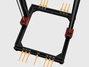
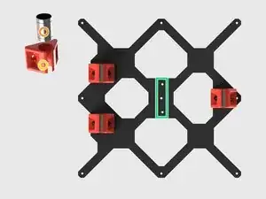
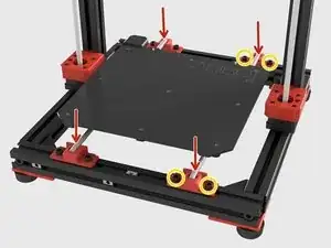
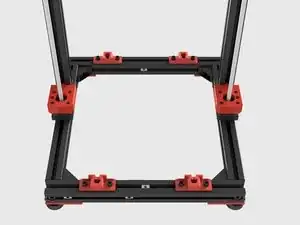
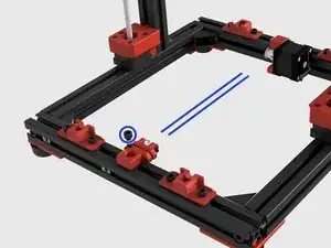
Insert 7 x T-Nuts in front extrusion and 6 x T-Nuts in the back.
-
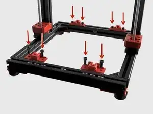
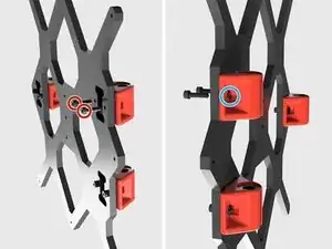
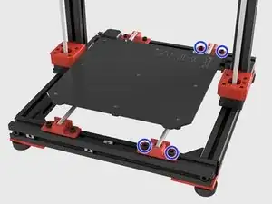
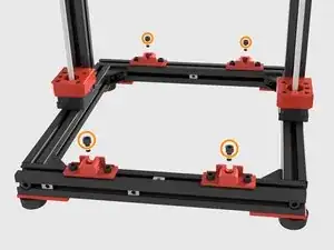
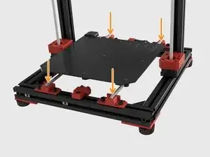
Use 8 x M6x12 screws to fasten the Y rod holders in their places. but do not tighten them as you will need to move them to aling the rods in position.
-
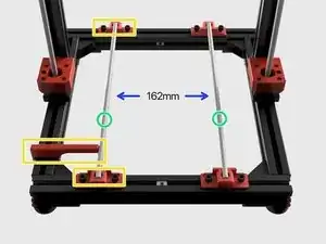
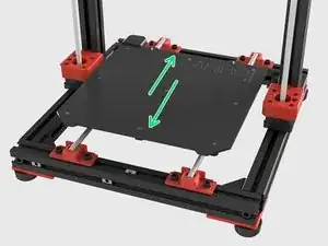
Attach 2 x 360mm hardened steel smooth rods and do not final position them yet.
-
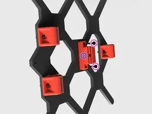
Align the left rod at front and back with the alignment tool provided. Tighten the M6 screws after alignment.
-
Distance between rods should be 162mm. The best alignment method is using the heatbed carriage with bushings to naturally align the rod on the right so do not final tighten the M6 screws of the rod on the right for now. You will be doing this on the following steps.
-
-
-
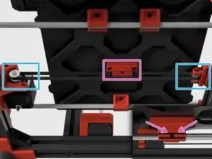
Insert the 3 x Misumi LM8UU bushings to the Y carriage bearing holders.
-
Y carriage bearing holders are not directional. There are two tiny bumps inside the holders to hold the bearings in place.
-
Before assembling the bearing holders ensure that the hole in the middle of the y carriage is aligned to left.
-
Use 2 x M3x14 screws for each bearing housing.
-
Use 2 x M3 Hex Nuts in order to tighten the screws.
-
Y axis belt holder should be faced to two bearings on the left.
-
Use 2 x M3x14 screws to fasten the belt carriage as seen in the picutre. Holes on the Y carriage for the belt carriage are tapped and you don't have to use nuts to fasten them.
-
-
-
Position the Y carriage with the MK52 heated bed as seen in the picture. Two bearings and the heated bed cable output should be on the same side.
-
Use 9 x M3x10 countersunk screws to mount the heatedbed to Y carriage.
-
Insert 9 x 5mm spacers between the MK52 heated bed and the Y Carriage
-
-
-
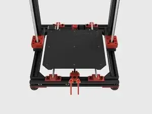
Release the M6 screws on the right rod holders to be able to move and align them with the right Y rod.
-
Push down the Y rods in to the gaps on the Y rod holders.
-
Before tightening the M6 screws on the right Y rod holders, gently move the MK52 Heated Bed back and forth down to the edges several times and let the rod holders to find their correct position.
-
Ensure the heated bed is moving freely and tighten the m6 screws on the right Y rod holder.
-
-
-
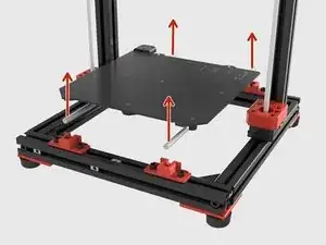
Gently pull the Y rods up from the edges and remove the MK52 Heated Bed, Y Carriage and rods from XY Frame.
-
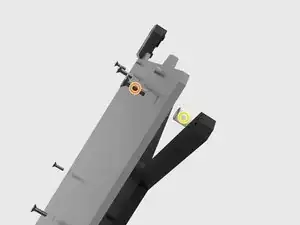
Insert 4 x M6x12 Socket Head screws into the middle holes of the Y rod holders and tighten them. These screws are going to keep Y rod holders in place while you are assembling the Y rod holder covers.
-
-
-
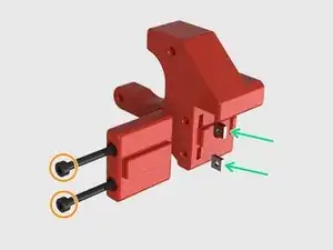
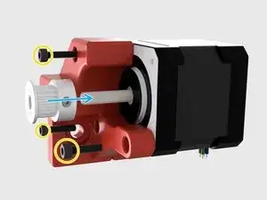
Insert 2 x M3 Square Nuts in to their places on the Y Motor holder.
-
Use 2 x M3x40 Socket Cap Screws to assembly Y motor support to the motor holder.
-
Mount the motor to the holder with 3x M3x14 Socket Cap Screws
-
Push the GT2 16T pulley to the motor shaft and ensure that one of the tightening screws are landing on the flat surface of the motor shaft, tighten the 2x M2 hex pulley screws to fasten the pulley on the shaft.
-
Use the supplied Y motor alignment tool to position the motor.
-
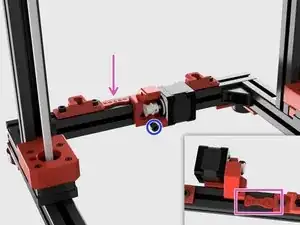
Mount the Y Motor holder with a M6x14 Socket Cap Screw.
-
-
-
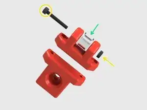
Place the belt idler pulley in its place.
-
Use M3x20 Socket Cap Screw and M3 nut to fix the idle pulley. Do not too tighten, idle pulley should turn freely.
-
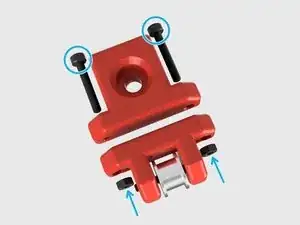
Mount 2x M3x20 Socket Cap Secrews and 2x M3 Nuts and tighten them equally. Leave 5mm distance between the idle pulley piece and extrusion mount piece.
-
Use a M6x14 Socket Cap Screw to mount the tensioner. Ensure that idler pulley and GT2 motor pulley are aligned. This is not the latest alignment, so do not final tighten.
-
-
-
Put the heated bed assembly in its place and slightly push the rods to holders.
-
Pass the GT2 belt from idler pulley and motor pulley. Teeth should be inside.
-
Insert the belt ends to the toothed gaps in the Y Belt holder. Try to make it as tight as possible but to not force to make it as tight as it should be. Because you have the belt tensioner for this purpose.
-
Tighten the belt with the tensioner. Turn the two screws in order, one full turn each time. As a tension, the belt should "twang" when you flick with your finger.
-
To reassemble your device, follow these instructions in reverse order.
5 Kommentare
Hi,
you wrote GT2- Pulley 20T but it is a 16T Pulley. Isn’t it?
Yes, it is fixed now.
Do you know where to getr the misumi 360mm hardened steel smooth rods for x-axis and the 420 mm for z-axis?
And can you also tell me if the parts here like Rambo Ensy Board, heatbed and steppers are from the same manufacturer because there are no specs about this. Thanks.
-> Hard Chrome Precision Linear Shaft - Straight 360mm (x) is also wrong. It’s 370 mm ;)
