Einleitung
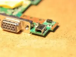
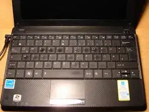
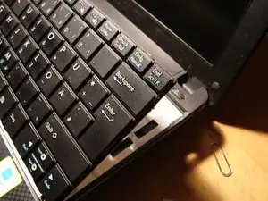
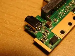
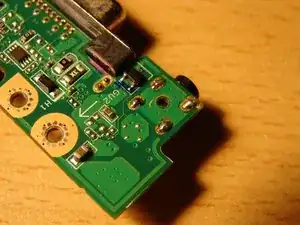
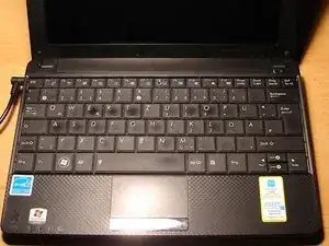
I will walk you through the steps on how to replace a broken charging socket on an ASUS Eee PC 1001PX
Werkzeuge
Ersatzteile
-
-
Prepare the PC: Shut it off and remove the charging cable (left).
-
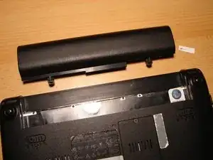
Turn the PC and unlock the battery switch in order to remove the battery.
-
-
-
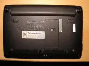
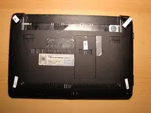
Unscrew the five screws as shown on the picture (see the arrows).
-
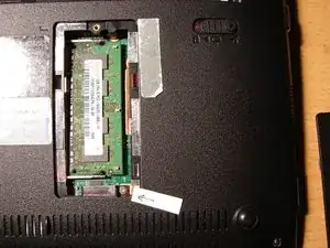
Remove the lid of the RAM (located to the right of the Microsoft label).
-
Remove the RAM and unscrew the single screw (see arrow).
-
-
-
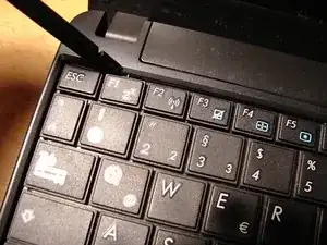
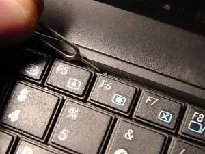
The keyboard is held by several clamps located at the top of the keyboard. Use a paperclip or pryer tool and push in all of these clamps.
-
Carefully pry out the keyboard. The bottom part of the keyboard might stick on, so be gentle. Also keep in mind that the ribbon cable of the keyboard (which is under the keyboard) is still attached to the motherboard. Don't remove it yet!
-
Gently lift up the keyboard as seen in the third picture and go to the next step. Again, don't remove the keyboard yet, otherwise you might damage/tear apart the ribbon cable!
-
-
-
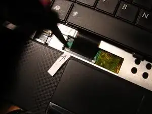
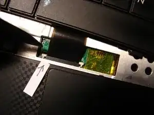
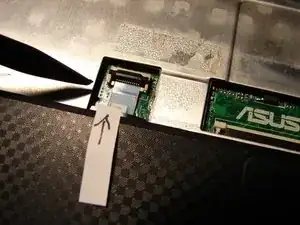
Gently unlock the holder of the ribbon cable of the keyboard by using a plastic tool.
-
You unlock the holder by pushing the white part on the left side (where the arrow is) toward the screen of the PC. Do the same on the right side.
-
Gently pull out the ribbon cable. Now you can finally remove the keyboard unit.
-
-
-
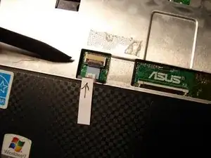
After having removed the keyboard, you will see the ribbon cable of the touch pad cable that needs to be removed (it is located to the left of the ribbon cable holder of the keyboard).
-
Gently unlock it by lifting the holder (black part) with a plastic tool. The ribbon cable has a lug which makes it easy to pull it out of the holder after the holder is lifted.
-
For your information: This blue ribbon cable needs to be removed before - in the next step - the upper part of the PC is removed.
-
-
-
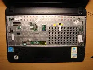
Remove all the screws shown in the picture (see arrows).
-
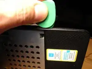
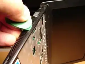
Next, gently pry the upper part with a plastic tool along the edge(s), as shown in the pictures. Be careful and patient! When prying out the upper part, you need to hear it 'click' . Every 'click' indicates that at that place the upper part is released from the lower part.
-
For your information: It is the upper part that needs to be removed, not the lower part. The lower part keeps and holds the mainboard and other parts, as you will see in the next step.
-
-
-
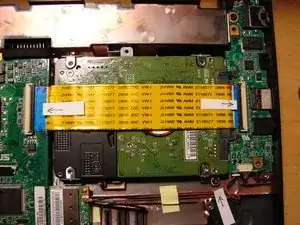
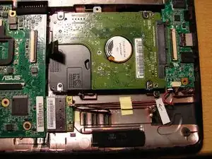
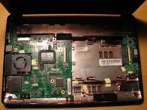
After having removed the upper part, you will see the inner workings of your PC. In a first step, you at least need to remove the yellow cable of the Hard Drive. You don't necessarily need to remove the Hard Drive, however, I recommend it due to reasons of more space.
-
Gently unlock the ribbon cable holder (see arrows) in the same way you removed the blue ribbon cable of the touch pad earlier.
-
-
-
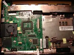
Unscrew the two screws of the motherboard as shown (see arrows).
-
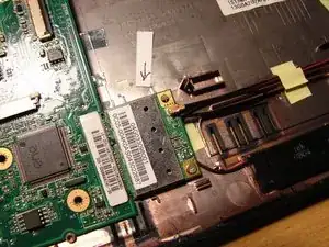
Next, unscrew the screw of the Wifi unit and remove it together with the Wifi unit. You just need to pull the Wifi unit out of the plug.
-
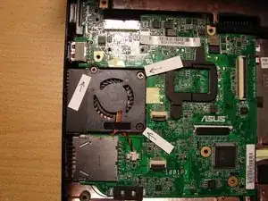
Unscrew the three screws of the fan (see the arrows on the third picture). The fan remains on the motherboard, you don't have to remove it.
-
-
-
Carefully lift the mainboard. Start on the right sight by lifting it up gently about half an inch. Take your time!
-
When lifted up, pull it slightly to the right while at the same time gently moving/prying it forth (toward the screen of the PC) and back. The mainboard is 'fixed' mainly through the VGA port, so you might want to check around that area during this process.
-
Before you finally remove the mainboard, you need to unplug the cable of the LCD screen unit. The cable is attached on the mainboard on the top left (silver plug). Gently pry it out of its silver holder.
-
-
-
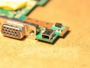
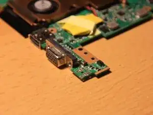
After having removed the mainboard, you need to turn it. You will now see the broken charging plug to the right of the VGA port.
-
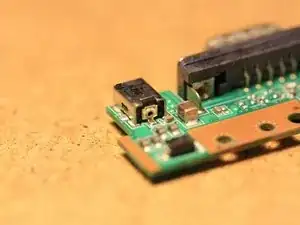
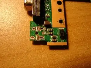
Assess the damage. The charging plug you see here cannot be repaired any more but needs to be replaced.
-
The charging plug is soldered to the PCB professionally. So, you might want to take some extra time for the next step(s).
-
-
-
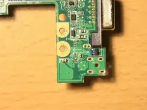
Use a soldering iron or soldering station to unsolder the broken charging plug.
-
Keep in mind that the solder used by ASUS is industrial solder. Therefore, it needs a soldering iron or soldering station of at least 40 W. A mini soldering iron with 15 W will not do!
-
In case you do not have such a powerful soldering station or soldering iron, you can use a mini drill to mechanically remove the charging plug one piece at a time. This takes time, but when done successfully, you can then unsolder what is left of the charging plug, for example the legs on the PCB.
-
Again: Take your time with the unsoldering process. Also, don't put too much physical pressure on the PCB area around the charging plug. The PCB could break at that place when pushed too much.
-
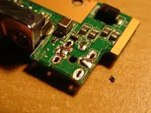
One important tip: Use desoldering wick while unsoldering the charging plug. The wick will soak in melted solder. When the broken charging unit is successfully removed, use desoldering wick again to clean all solder joints of the pins of the charging plug on the PCB.
-
-
-
Congrats! You have successfully removed the old charging plug. Now, put some new solder onto the cleaned solder joints - but just a bit, not too much! Pay attention that the openings of each solder joint of the charging plug remain open!
-
The moment has come to put in the new charging plug. One very important advice before you start soldering: Start soldering on the top side of the PCB, not on the bottom side! This is critical since the two middle pins of the new charging plug need to be soldered first, including the pin on the back side of the charging plug.
-
Now push the new charging plug into the openings (again: on topside of the PCB!). Next, decide, which middle pin you want to solder first (right or left?).
-
Gently push either the right or the left side of the charging plug down with a wooden part (since the metal part of the charging unit gets really hot!) while you are soldering this pin (this is why we prepared the solder joints with a bit of new solder). Do the same with the other middle pin and finally with the pin on the back side.
-
Now take care of the legs of the charging plug on top of the PCB. Give all solder joints a final touch before you finally turn the PCB and finish the soldering job there by soldering the four solder joints. Job done!!
-
To reassemble your device, follow these instructions in reverse order.
Ein Kommentar
Nice work steffen brother
