Einleitung
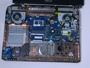
If you have connectivity issues due to defective hardware, this guide will show you how to access, remove, and replace the WiFi chip in your ASUS unit. This particular replacement can get fairly involved, and requires the removal of the keyboard plate, and must therefore be executed with a lot of caution.
Werkzeuge
-
-
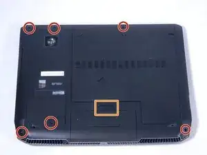
Remove the 6 screws on the edge of the laptop using a screwdriver.
-
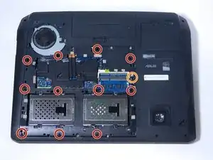
Remove the back casing being held on by the one single screw. First, lift the casing at the edge where the screw once was, then carefully lift at the rest of the edges to loosen the casing. Pull the casing towards the edge where the screw was.
-
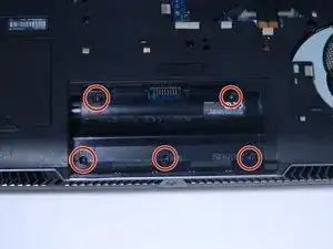
Remove the battery by sliding the switch circled in the picture and pulling the battery out.
-
-
-
Remove the 11 screws circled in the picture using a Phillips head screwdriver. They should be labeled on the laptop with a capital A, shown circled in red.
-
Remove the screw labeled C.
-
-
-
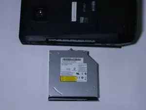
Remove the DVD ROM on the side of the computer, by pulling it out. If necessary, use a plastic opening tool.
-
-
-
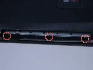
Remove the three screws located where the DVD ROM once was, on the screen side of the laptop.
-
-
-
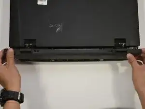
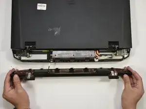
Flip the laptop over and pop the back cover off behind the screen, by grabbing it on either side and pulling it up, vertically off of the laptop.
-
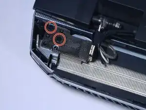
There is a cable connecting the cover to the laptop, shown in picture 2.
-
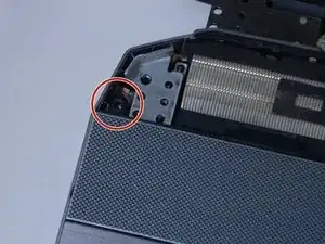
Disconnect the cable by pulling apart the white connectors, shown in picture 3.
-
-
-
There will be two smaller and two larger black screws on each hinge holding the laptop screen onto the computer. Remove all four of the larger screws with your P0 screwdriver.
-
There is one screw on either side of the keyboards, next to the screen hinges. Remove both screws.
-
-
-
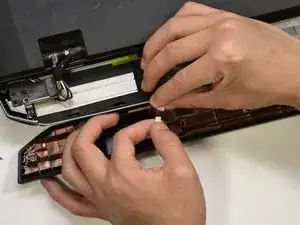
You may now remove the keyboard plate. Simply lift from the back, and pull it off all the way around.
-
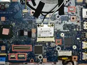
Caution with removing the keyboard, as there are 5 ribbon cables that connect the motherboard to the keyboard (motherboard port locations shown in picture 2).
-
The ribbon cables must be carefully disconnected from the motherboard side, by flipping a latch on the port and pulling the ribbon out.
-
-
-
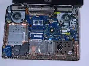
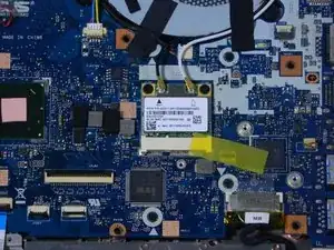
If you look between the fan (upper right in the first picture), and the hard drive bay (lower right), there is a small white square. (Enlarged in second picture) This is the WiFi chip.
-
-
-
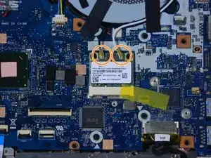
If you look at picture one, circled are the micro-coaxial cables that connect the WiFi chip to the screen. These simply pull off.
-
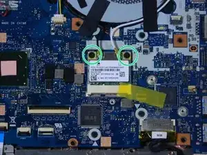
Picture 2 has circled the screws that connect the WiFi chip to the motherboard. Remove these with your P0 screwdriver, and the chip will slide out away from its white port.
-
The WiFi chip is now disconnected, and ready to be replaced with your new one.
-
To reassemble your device, follow these instructions in reverse order. Make sure that you reconnect the micro-coaxial cables to the correct terminals. The terminals are labeled with small colored triangles.
