Einleitung
This guide will help you identify, remove, and potentially replace the memory modules within the Acer Aspire V5-591G-75KE.
Acer Aspire V5-591G-75KE is manufactured with two DDR4 SDRAM memory card slots with a standard capacity of 16 GB and a maximum of 32 GB.
Werkzeuge
Ersatzteile
-
-
Close down the display and flip the device upside down.
-
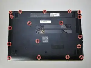
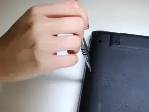
Use a Phillips #1 screwdriver to remove 18 black 10mm Phillips Head screws in order to loosen up the protective bottom casing.
-
-
-
With the screws removed, flip the device right-side up and open up the display.
-
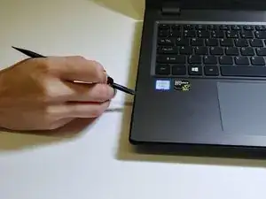
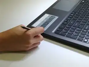
Run a plastic spudger tool along the seam of the face-plate in order to loosen up the protective bottom casing.
-
-
-
Close the display down once more, and flip the laptop upside down, with the hinge facing away from you.
-
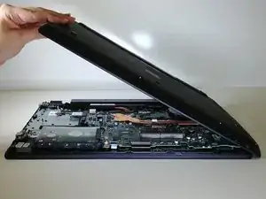
Taking note of the small speaker wire, gently lift only the left side of the bottom casing.
-
-
-
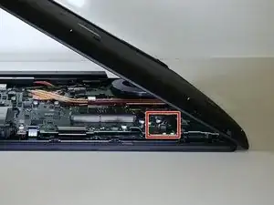
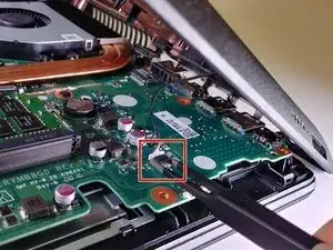
Using a pair of blunt tweezers, push on the tabs of the small white connector to separate it from the motherboard.
-
-
-
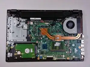
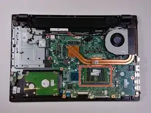
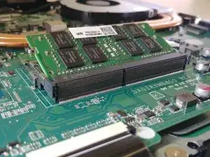
Locate the memory modules at the bottom right quadrant of the motherboard. The two memory modules are slightly stacked on top of each other.
-
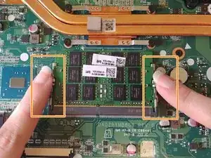
Using both hands, pull the clasps away simultaneously in order to release the memory modules.
-
-
-
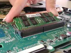
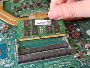
To remove the top memory module, lift the module slightly up and pull away.
-
Repeat the previous step to remove the bottom memory module.
-
To reassemble your device, follow these instructions in reverse order.
Ein Kommentar
Great job on the guide! looks very professional!
Aiden -


