Einleitung

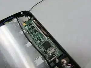
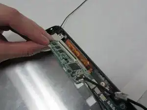
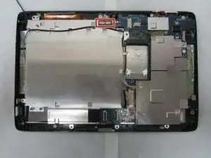
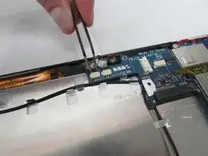
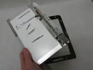
A display shows you what is happening on your device. Without a working display, a device isn’t much use. This guide will show you how to replace the display on your Acer Iconia Tab A501.

  1. 4eXEkKNX1ZDBtK1y
    4eXEkKNX1ZDBtK1y
    T4B1xjJCCHvnyAWn
    mECZH6AlgV13y1YQ
    • Turn off your device before opening it.

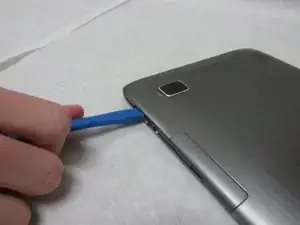
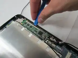
    • Use a plastic opening tool to carefully separate the back cover, starting at the volume buttons.

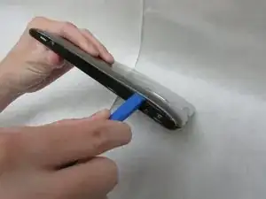
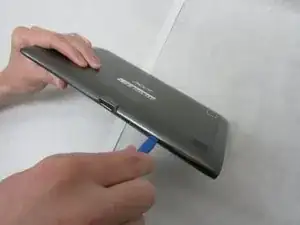
    • Continue separating the back cover along the short side closest to the camera and around the device.

  2. TJWQQdBWE5YOZHgi
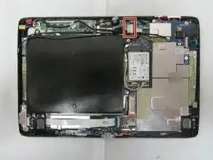
    • When separated enough, a little more than halfway around the device, the back cover will be easy to take off.

    Can this be combined with the previous step? I think you could lose one of the images before to condense.

    Alex Watkins -

  3. kop2siVsGIJCQF5n
    • Remove all tape from the device.

  4. QmLMqPWNdfcFUBPT
    QmLMqPWNdfcFUBPT
    UAw1FNQXXmnOrccW
    1EDANIVTQOSvPmT4
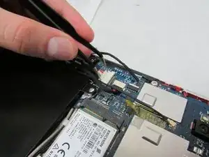
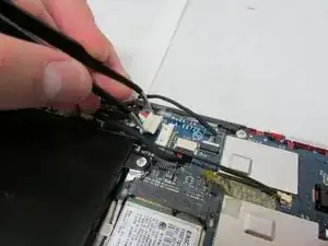
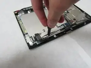
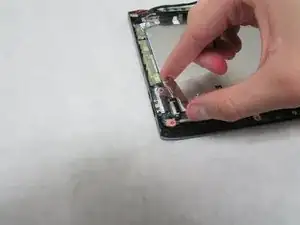
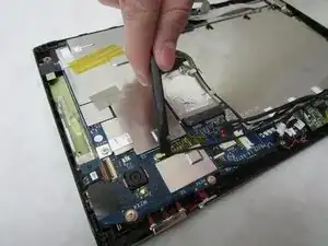
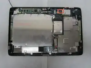
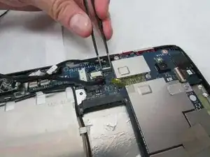
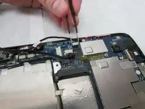
    • In the next step, be careful not to squeeze too hard or scratch the motherboard.

    • Use the angled tweezers to disconnect the motherboard-battery cable from the white connector in the middle of the side opposite the docking port.

  5. BqPVTmJao5FXMfDe
    BqPVTmJao5FXMfDe
    SCmnpEOXLhbvAtqk
    xLTJYIq5OXqJikOA
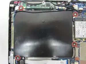
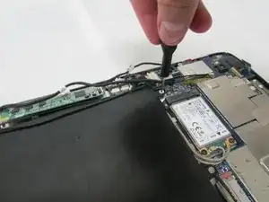
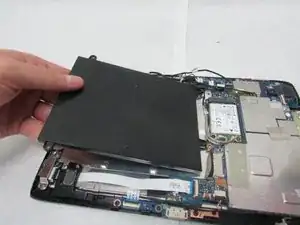
    • Use a Phillips #1 screwdriver to remove the four 4.0 mm Philips head screws connecting the battery to the motherboard.

    • Take out the battery.

  6. KXdIlxVfBnNfgTOr
    KXdIlxVfBnNfgTOr
    ZVNRZJqvcaYM2VJH
    dIoNuyQLWqtTKGHi
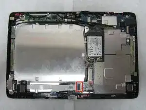
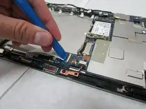
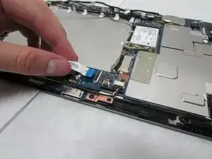
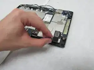
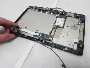
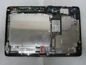
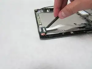
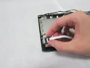
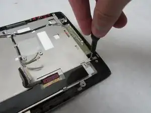
    • Use the plastic opening tool to flip up the locking mechanism on the motherboard connected to the folded, white ribbon cable.

    • Remove the folded, white cable.

  7. NN4xiKlp6okitcVL
    NN4xiKlp6okitcVL
    k2AvafbPNDZcCCv6
    nTbBx2RvWAAYrfK4
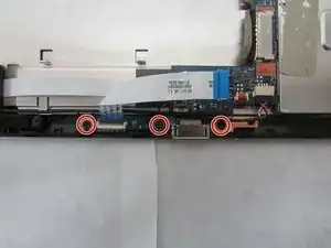
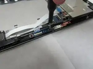
    • Use a Phillips #1 screwdriver to unscrew the three 3.0 mm Philips head screws holding the docking port in place.

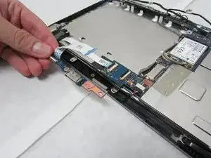
    • Remove the docking port.

  8. mI2OCUNSJNl1vTwi
    mI2OCUNSJNl1vTwi
    MAHWlOT33FYUnQOI
    UG1pkEJLIMJntRCK
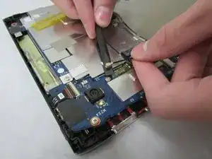
    • In this step, be careful not to squeeze too hard or scratch the motherboard.

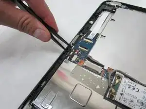
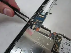
    • Use the angled tweezers to disconnect the cable with red, white and green wires from the beige connector slightly in from the docking port.

  9. YIVJVCi5VKeu3Fkt
    YIVJVCi5VKeu3Fkt
    QSE1GVNtTdbWsNxr
    puwVVUJObV5f2xh6
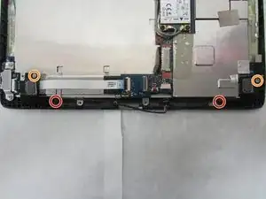
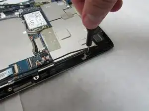
    • Unscrew the 3.0 mm Phillips head screw on each speaker using a Phillips #1 screwdriver.

    • Unscrew the 4.0 mm Phillips head screw on each speaker using a Phillips #1 screwdriver.

  10. ZX5tmKODfI2EOVFo
    ZX5tmKODfI2EOVFo
    lIJe6ymRYX3SYKSd
    • Remove the speakers.

  11. JO1dTwLqrtpXEXDR
    JO1dTwLqrtpXEXDR
    WUsEh1fAomnxrX35
    RNuyOsqG6LakObo4
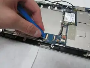
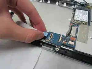
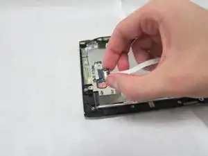
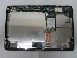
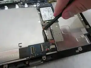
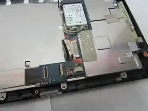
    • Use the plastic opening tool to flip up the locking mechanism on the motherboard connected to the straight, white ribbon cable.

    • Remove the straight, white ribbon cable.

  12. Q2OeBfKBDn2ddIvX
    Q2OeBfKBDn2ddIvX
    AMgWQ4tkO3GSkvQJ
    P3IsOCDu12LpCC1I
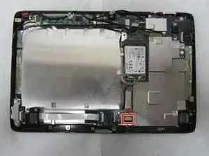
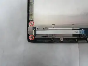
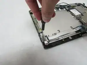
    • Use a Phillips #1 screwdriver to remove the two 4.0 mm Philips screws attaching the metal plate, USB board, and device.

    • Remove the metal plate.

  13. T1kHCyiEasrwvyEy
    T1kHCyiEasrwvyEy
    v56FtXj3vVVhxgg1
    eSaNJgUvayBxrVTs
    • Use the Halberd Spudger to carefully pop up and take out the ports.

  14. bL1PTUiL2ur4NvrE
    bL1PTUiL2ur4NvrE
    VZEUWqUWEExtcBsF
    6MYWWkZvRLGKUbZZ
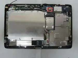
    • Use care in the next step.

    • Use the wide, flat end of the standard Spudger to disconnect the display connector from the large, metal port next to the battery space.

  15. PGuKeEJRRk3NxPsh
    PGuKeEJRRk3NxPsh
    BHnVIWlPUiKMkgS6
    rsAHO2Jnq5djDk45
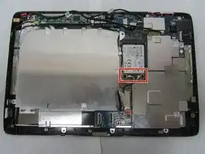
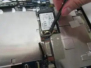
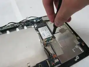
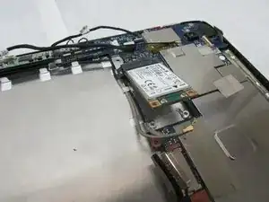
    • Use the flat end of the standard Spudger to disconnect the two small, rotatable connectors attached to the wireless adapter.

  16. FQ3bpaLfnVUcCW41
    FQ3bpaLfnVUcCW41
    qrYA4Kikp23ThPYF
    jGyKSvJqJS4hp4se
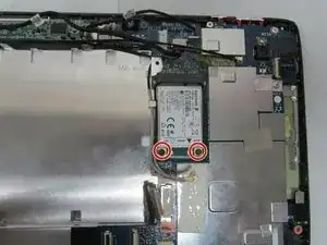
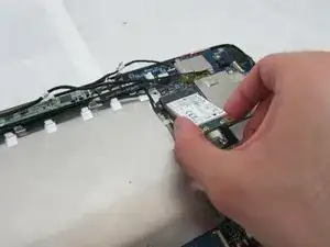
    • Use a Phillips #1 screwdriver to remove the two 3.0 mm Philips head screws holding the adapter down.

  17. o2tmCUNGROHxwNrZ
    o2tmCUNGROHxwNrZ
    gmEjVSAYBSEP2Mwd
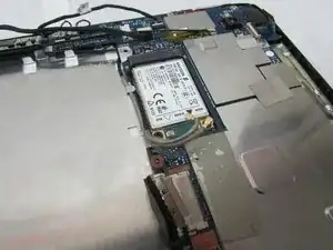
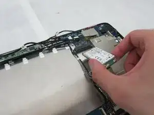
    • Carefully slide the adapter out to remove it.

  18. a5TLvj1CKuVbsfjT
    a5TLvj1CKuVbsfjT
    FMyCyiaejTHVgWyN
    eJ5YqjJQHGGXnixR
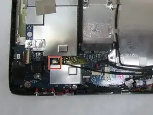
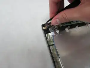
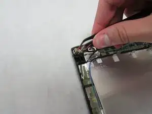
    • Use the wide end of the standard Spudger to take off the rotatable connector to the 3g antenna below the rear-facing camera.

  19. 1fWRfAWhxJaGwWDH
    1fWRfAWhxJaGwWDH
    KjPkB1WCD5b26Vl5
    y2LqurXvGbrq1UPy
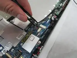
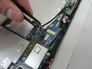
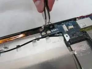
    • In the next step, be careful not to squeeze too hard or scratch the motherboard.

    • Use the angled tweezers to disconnect the cable with red wires from the beige connector opposite the docking port.

  20. RdETogXrSXWDUlJc
    RdETogXrSXWDUlJc
    fQ1Gln6MlIUvBIbJ
    aAFIoUNPw5MMayYS
    • The charging port may be taped from underneath and need a bit of force to take out.

    • Use the angled tweezers to remove the charging port.

  21. 2AjNfNqlVDxCHlVl
    2AjNfNqlVDxCHlVl
    NwIZfrKZMf5gtrNg
    k2pk5VFBashB3wHj
    • In this step, be careful not to squeeze too hard or scratch the motherboard.

    • Use the tweezers to remove the white touchscreen connector with multi-colored wires from the black port just below the power buttons on the motherboard.

  22. jcS5BPfn6n1KasJF
    jcS5BPfn6n1KasJF
    Xr1nnEVERZcZPeFD
    5MrvrUJ5ULQSx32A
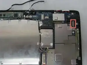
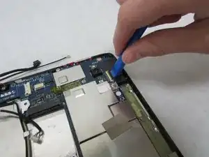
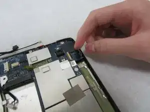
    • Use the plastic opening tool to flip up the locking mechanism for the wide, white port for the thin, orange-brown touchscreen cable just above the charging port.

    • Remove the touchscreen board.

  23. h5MbYjayPdrBdtRA
    h5MbYjayPdrBdtRA
    juFV4sfuV1mZKiqx
    DfUJKEHFyWcknd3n
    • In this step, be careful not to squeeze too hard or scratch the motherboard.

    • Use the angled tweezers to disconnect two microphone connectors, which are above the orange-brown touchscreen connector and next to the battery space.

  24. YxUgxQ3CcittIBLG
    YxUgxQ3CcittIBLG
    RuOWFgYVeKVmwCDt
    ix1x5v3oy41kbXKL
    • Use the plastic opening tool to flip up the locking mechanism to the white front camera port just above the rear-facing camera.

    • Disconnect the camera cable from the motherboard.

  25. wqZRS2HbsBLhhVwv
    wqZRS2HbsBLhhVwv
    Lnq3FTg1fNUsnSRZ
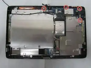
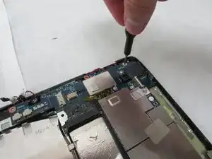
    • Use a Phillips #1 screwdriver to unscrew the four 4.0 mm Phillips head screws holding the motherboard in place.

  26. PHcXwKdpEJ4eJa4S
    PHcXwKdpEJ4eJa4S
    OZYDtNxLuvSyjnxo
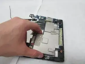
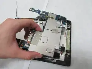
    • Remove the motherboard.

  27. CNo2xXKlWTDthoII
    CNo2xXKlWTDthoII
    bIQUBQWGqXvQvsUW
    qqeQecqJ5HuDtPBF
    • Remove the two microphones in the middle of the side opposite the docking port.

  28. umjZP6V6CE2wWdtR
    umjZP6V6CE2wWdtR
    vTKgHg6aWIJRAqea
    • Use the Phillips #1 screwdriver to unscrew the 3.0 mm Phillips head screw holding the thin metal plate to the device near the Micro-HDMI port.

    • Use the Phillips #1 screwdriver to unscrew the 4.0 mm Phillips head screw near the orange-brown touchscreen cable.

  29. fl2hNNZAH2PHj1Ej
    fl2hNNZAH2PHj1Ej
    JjJa16MeBJrydx1k
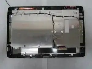
    • Move all wires off of the thin, metal plate.

  30. e645Hsr5PtArLSKQ
    • Remove the metal plate.

  31. DCFpsNyNSuAmlyuC
    DCFpsNyNSuAmlyuC
    N4VnlfpfeaBQWfgP
    rF5m1gt4RQHPgag4
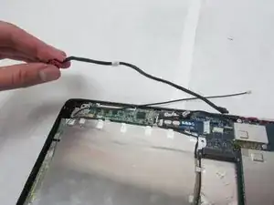
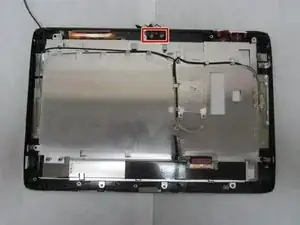
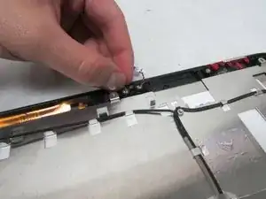
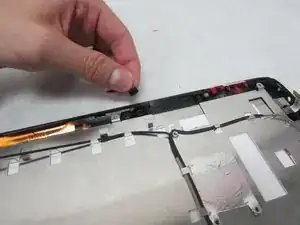
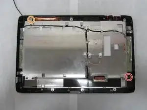
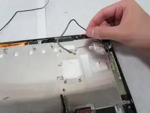
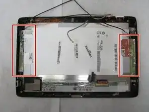
    • The antennae in the next step are attached with adhesive.

    • Remove the three antennae along the shorter sides of the device.

  32. bm25CCq4FUHGZjMZ
    bm25CCq4FUHGZjMZ
    FURvZC6IMflgrSGX
    yGEpA5eFDhW3JVtk
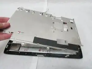
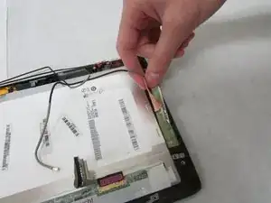
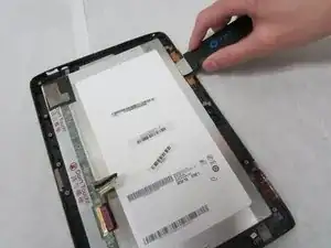
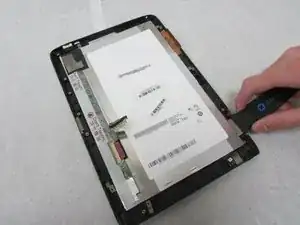
    • Carefully insert the Jimmy between the display and the glass to break the glue seal.

    • Move the Jimmy all the way around the device.

  33. SjgPB6jPWxYtDEPL
    SjgPB6jPWxYtDEPL
    YdW4CTXjtVdSQVPj
    tYepqYqEQuMxmWrW
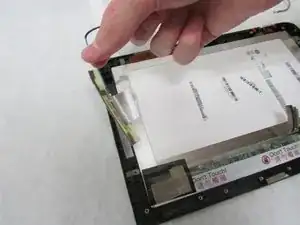
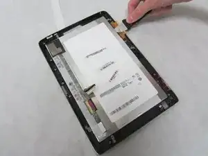
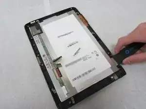
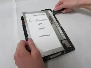
    • Continue moving the Jimmy around the device until the glue no longer holds the display in place.

    • Remove the display.

    Should the first step here be combined/condensed into the previous step?

    Alex Watkins -

Abschluss

To reassemble your device, follow these instructions in reverse order.
Daksh Malhotra

Mitglied seit: 08/07/19

1383 Reputation

0 Kommentare