Einleitung

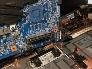
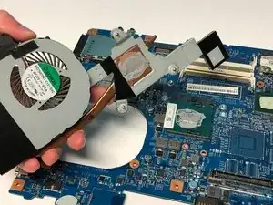
The Acer TravelMate P653-V-6882 may tend to overheat during use caused by the slots/ports being blocked, dust in the fan, inadequate amount of thermal paste, or a thermal unit failure.

Excessive amount of heat generated within the laptop may cause harm to the components of the laptop. By gaining access to the thermal module, this will let you add thermal paste, clean the fan, and replace the thermal unit.

If you tried cleaning the dust in the fans, adding more thermal paste, and clearing the blocked slots/ports, you must then remove and replace the thermal module.

Before you begin replacing the thermal module, ensure the laptop is fully powered off and any external power is removed.

  1. LRlKCWJR5jLPU1rm
    LRlKCWJR5jLPU1rm
    vQdk22nlsyOVpg11
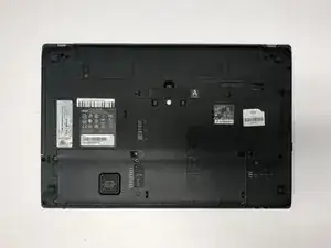
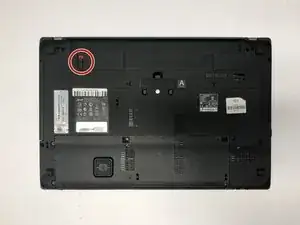
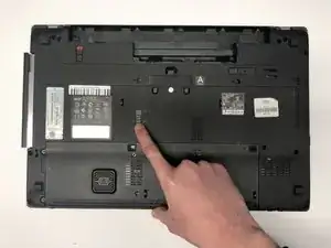
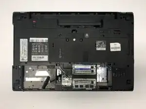
    • Turn the computer over so the base is facing up.

    • Slide the battery lock to unlock position.

  2. aCVFOFemWMbqEYcx
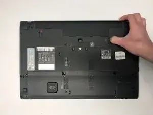
    • Slide the battery release latch to the right.

    • The battery pack will pop out.

  3. wQto2QuPdWLWMNYI
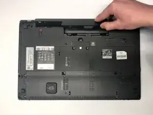
    • Lift the battery up.

    • Pull out the battery.

  4. AkGclVqhFZmn1OqX
    • Slide the ODD module latch down.

    • The ODD module will pop out.

  5. xi1e3mykOwPUGJre
    • Remove the ODD module.

  6. wdfKvqWYhCoWcKkn
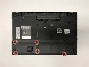
    • Remove the five 7mm Phillips #1 screws.

  7. kIuLHwsRCp1NZOSJ
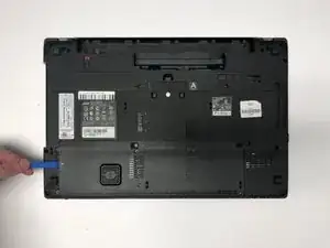
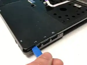
    • Use the opening tool to separate base door from the bottom of the laptop.

    • Be careful not to bend or crack the plastic back cover.

  8. EKyUHNkGYYT3Vqfy
    EKyUHNkGYYT3Vqfy
    aDkSjG4oaKaCYKKf
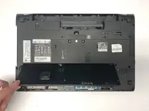
    • Gently pry open the base door by pushing up.

    • Pull out the base door.

    • Be careful not to bend or crack the plastic back cover.

  9. sTHNQSGkWt3SEeok
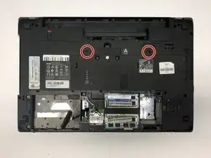
    • Remove the two 7mm Phillips #1 screws.

  10. kvIYZQxYYQmNagO4
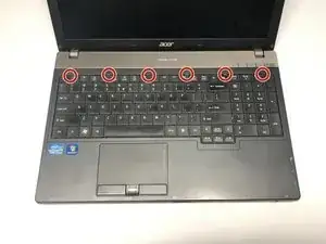
    • Flip the laptop so that the underside is now facing the bottom.

    • Open the LCD panel.

    • Use the flat end of a spudger to push in the six latches.

    • Be careful not to bend or crack the keyboard.

  11. VtGmhGF6xhmgVOTY
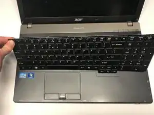
    • When the latches are pushed in, the keyboard will pop out.

    • Gently pry up the keyboard.

    • Be careful not to bend or crack the keyboard.

  12. tRaP5bIYAPRRhQPw
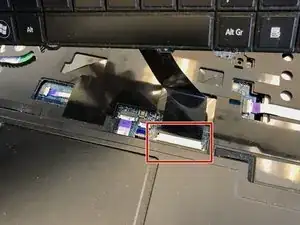
    • Slide the keyboard forward to access the keyboard cable.

    • Flip the connector latch up to open it.

    • Pull out the keyboard cable gently.

    • Be careful not to damage the connector.

  13. G3JgZesehMYVEHKu
    G3JgZesehMYVEHKu
    RTWrpAE2aaKdsmcv
    Lm5NkFBs4UpBx6dV
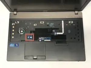
    • Turn the computer over, open the LCD panel, and find the smart card cable connector.

    • Open the smart card cable connector latch.

    • Disconnect the cable.

    • Be careful not to damage the connector.

  14. 1LG5bEMUDGRKQBrI
    1LG5bEMUDGRKQBrI
    nOOgf1nEF5n2QYXQ
    sGbT4KsdPZGmpaRq
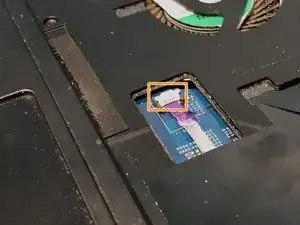
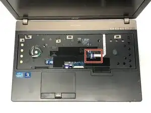
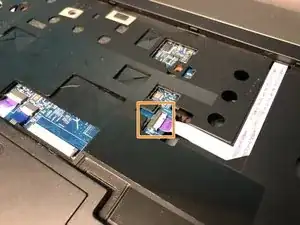
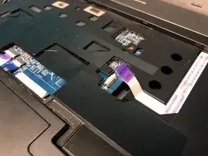
    • Find the power button launch board cable connector.

    • Open the power button launch board cable connector latch.

    • Disconnect the cable.

    • Be careful not to damage the connector.

  15. HogS3XELcaGohdGA
    HogS3XELcaGohdGA
    XCseyQkKnQmKPPUy
    qRbx1ZqdFQlskDJP
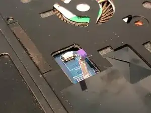
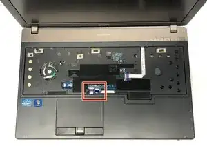
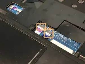
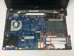
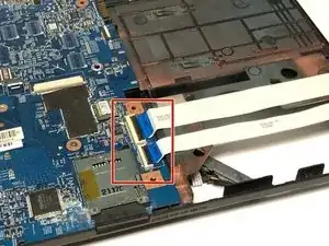
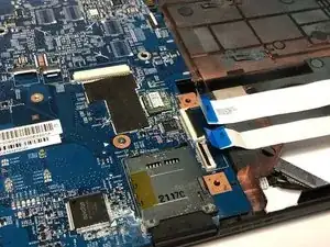
    • Find the touchpad and fingerprint board cable connector.

    • Open the touchpad and fingerprint board cable connector’s latches.

    • Disconnect the cables.

    • Be careful not to damage the connector.

  16. JcaTBqBVCihKq2EG
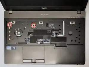
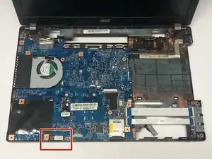
    • Using the #1 Phillips screwdriver, remove the two screws.

  17. 1QnTYhRAs1D4GJ6t
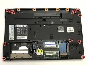
    • Flip the laptop over so that the underside is facing up.

    • Remove the twelve 7mm Phillips #1 screws.

    • Remove the five 3mm Phillips #1 screws.

    • Disconnect the cables connecting to the WLAN module.

  18. rMSOyRueZd1TBEUZ
    rMSOyRueZd1TBEUZ
    RGlmZEmG6nGTJCuN
    lRnEYfFKqVZx33iJ
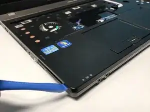
    • Flip the laptop so that the underside is now facing the bottom.

    • Open the LCD panel.

    • Locate the small gaps between the upper cover and lower case on the left and right side of the laptop.

    • Insert the opening tool into each gap to separate the one from the other.

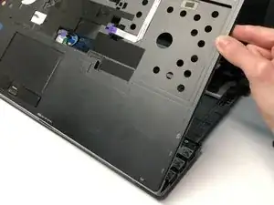
    • Once the upper cover is separated, lift it from the lower case.

    • Be careful not to damage the upper and lower case while removing.

  19. clnE2blusadiTaed
    clnE2blusadiTaed
    CqXZsd2K6KFsmLYd
    iayONl3QkOv2KDDH
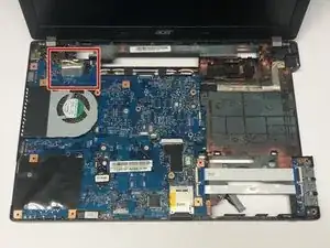
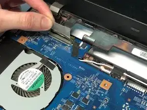
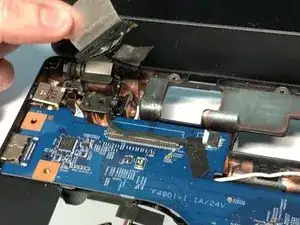
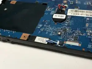
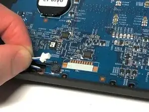
    • Detach the transparent tape securing the LCD cable.

    • Disconnect the LCD cable from the mainboard.

    • Be careful not to damage the LCD cable connector.

  20. ZnAaWHUCSmMGy5SB
    ZnAaWHUCSmMGy5SB
    VI6vMeGusXTCWUtt
    CcWlCoOOlxtgFFuD
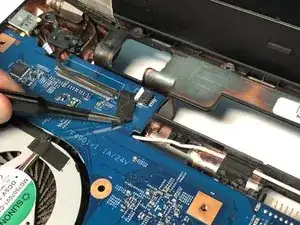
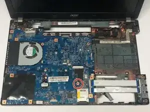
    • Detach the black tape covering the microphone cable.

    • Disconnect the microphone cable from the mainboard.

  21. fyTJKwLjvOiTtYFK
    fyTJKwLjvOiTtYFK
    SyoLE3MFpBjQTSrM
    iQdJaASGTQQrMGtP
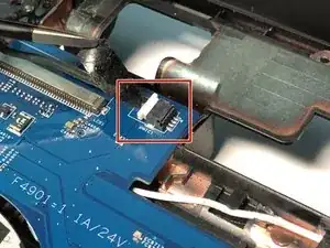
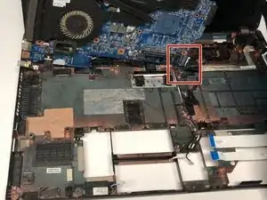
    • Open the USB board cable's connector latches.

    • Disconnect the cables.

    • Be careful not to damage the connectors.

  22. KtFibCZFidaX4XJd
    KtFibCZFidaX4XJd
    3um3wlWDTXfQrjOJ
    LxLIEIRHFQopFqks
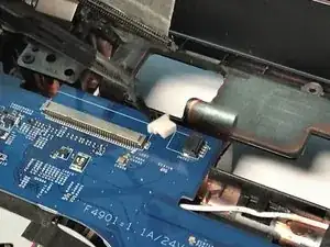
    • Disconnect the left speaker cable from the mainboard.

  23. YGNLOhvdaFTdDOww
    • Remove the one 7mm Phillips #1 screw.

  24. 2RrE52YEPTsEvIBL
    2RrE52YEPTsEvIBL
    IjwORJWIA2eRONfC
    • Lift the mainboard at an angle and gently turn it on its side.

    • Disconnect the LAN cable from the mainboard.

  25. aCb4ZmYAcMOVa1N2
    aCb4ZmYAcMOVa1N2
    1R5CAOZulE2agMVH
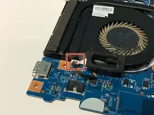
    • Disconnect the thermal module fan cable from the mainboard by pulling the cable directly upwards.

    • Be careful not to damage the connector

  26. uNnwgZ5JUKDRbbOD
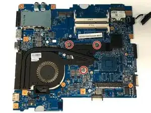
    • Loosen the three spring loaded Phillips #1 screws.

  27. pyrrmQ5lLsOBbgWh
    pyrrmQ5lLsOBbgWh
    A31YtdLpgaOFowKp
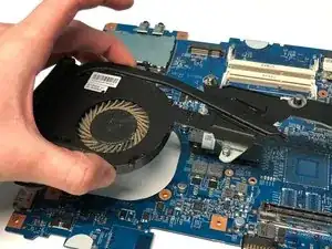
    • Lift the thermal module directly upwards

Abschluss

To reassemble your device, follow these instructions in reverse order.
Ryan Celzo

Mitglied seit: 14/01/20

97 Reputation

0 Kommentare