Einleitung
Use this guide if any of the selector knobs get bent, broken, or stops working.
Werkzeuge
-
-
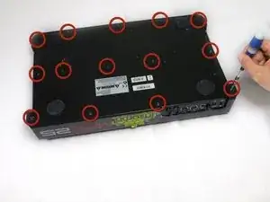
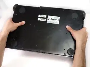
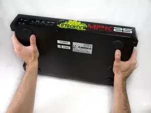
Flip the device over. Using a Philips #2 screw driver, remove the fourteen 10.3 mm black screws holding the back panel in place.
-
-
-
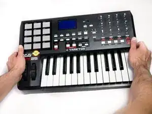
Carefully flip the device to the front making sure you secure the face plate and the chassis together.
-
-
-
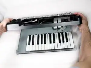
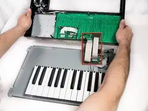
Rotate the device 180 degrees and carefully remove the face plate by slightly lifting the screen side towards you and then sliding the bottom out from under the keys.
-
-
-
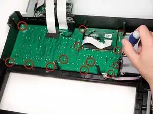
Using a Phillips #2 screwdriver, remove the thirteen 9.8mm silver screws holding the mother board to the face plate.
-
-
-
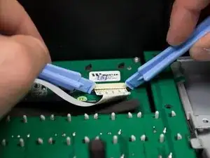
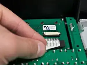
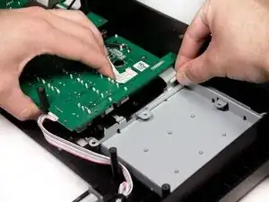
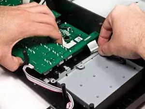
Using two plastic opening tools, slide the black locking mechanism on the ZIF connector towards you. This will remove the ribbon cable connecting the motherboard to the screen.
-
-
-
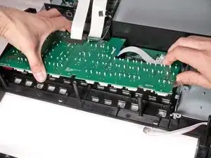
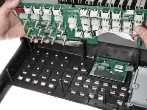
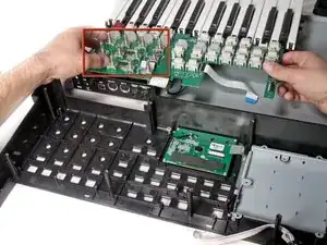
Remove the mother board completely from the face plate and identify the broken potentiometer.
-
-
-
Flip the mother board back over so the potentiometers are facing down and the leads are facing up. Then identify which leads correspond to the broken potentiometer.
-
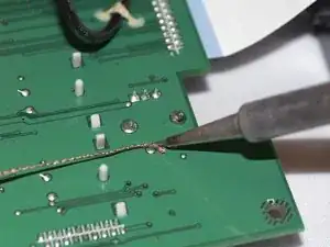
Use a soldering iron with solder wick (or a solder sucker) in order to free the potentiometer from the mother board.
-
To reassemble your device, follow these instructions in reverse order.
Ein Kommentar
Thanks for putting together this great tutorial. Does anybody out there have the part number of the potentiometer?
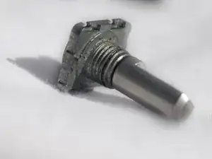
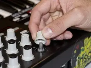
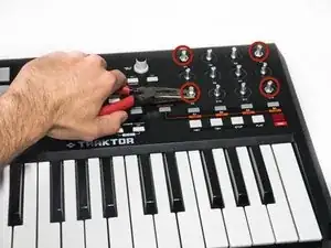

There’s NO need to remove all of the knobs in Steps 1 & 2…the faceplate lifts off with or without them attached.
NY Prince -