Einleitung

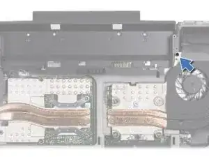
In this guide, we will show you how to remove and replace the Processor Fan and Heat-Sink Assembly.

  1. XIQIj1kvSxPCqaZx
    • WARNING: Before working inside your computer, read the safety information that shipped with your computer.

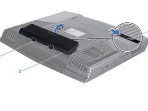
    • Turn the computer over.

  2. raExf1jfrPIQ3tPi
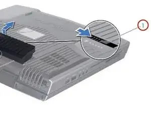
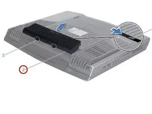
    • Slide the battery latch to the unlock position as shown.

  3. AyutB62CN52SMJ2d
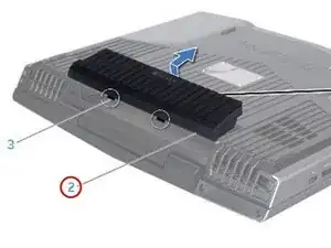
    • After the Battery Pack pops up, remove the Battery Pack.

  4. XMUESkW5Ei6RcjE1
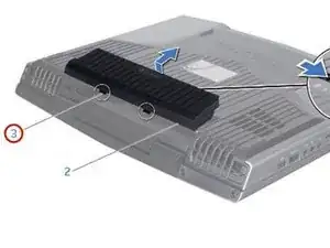
    • Align the battery pack tabs with the slots in the battery bay.

  5. 4XhgsGSYPIpbXCgD
    • Push the NEW battery pack into the battery bay until the battery pack clicks into place.

  6. lnEOSXeRIoLaBijK
    • WARNING: Before working inside your computer, read the safety information that shipped with your computer.

    • CAUTION: To avoid electrostatic discharge, ground yourself by using a wrist grounding strap or by periodically touching an unpainted metal surface (such as a connector on the back of the computer).

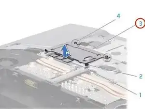
    • Loosen the two captive screws that secure the memory-module door to the computer base.

  7. HhfODQu4KXqrwusq
    HhfODQu4KXqrwusq
    cpDpgJMYDXoAfHtI
    • Slide the memory-module door to release the tabs and lift the memory-module door out of the computer base.

  8. th3pRVtNMpKfUntx
    th3pRVtNMpKfUntx
    J4wZnNBdDekwUfAd
    • CAUTION: If you need to remove memory modules from both connectors, remove the memory module in the upper connector before you remove the module in the lower connector.

    • CAUTION: To prevent damage to the memory module connector(s), do not use tools to spread the memory module spring-locks.

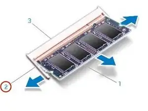
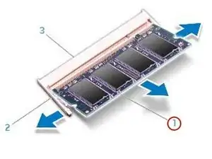
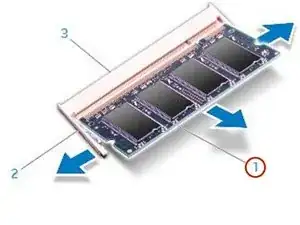
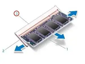
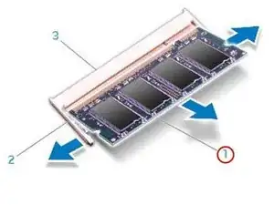
    • Use your fingertips to carefully spread apart the spring-locks on the memory-module connector until the memory module pops up.

  9. 6ltO1LcHMLGGGPGW
    • Remove the memory module.

  10. 2ERWCG6DUEqIMdZP
    2ERWCG6DUEqIMdZP
    Kt1FbglxmdDH2hpd
    KrOMA4imO44YSBmm
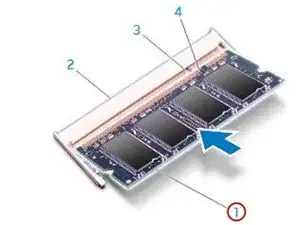
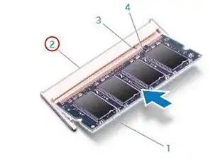
    • Align the notch on the NEW memory module with the tab on the memory-module connector.

  11. 2pGOtyNVAMFrhGNX
    2pGOtyNVAMFrhGNX
    kpa1YooOOHYHTuhS
    • Insert the module into the memory-module connector at a 45-degree angle, and press the memory module down until it clicks into place. If you do not hear the click, remove the module and reinstall it.

  12. hUSDITfvc15eUPjY
    hUSDITfvc15eUPjY
    hFFo4UCvVRNm4U4Q
    • CAUTION: If the memory-module door is difficult to close, remove the memory module and reinstall it. Forcing the memory-module door to close may damage your computer.

    • NOTE: If the memory module is not installed properly, the computer may not boot.

    • Align and insert the memory-module door tabs into the slots on the computer base.

  13. 2n3XKICSfjHyBnwK
    • Replace and tighten the two captive screws that secure the memory-module door to the computer base.

  14. eLs6dLXcroHF1Iru
    • WARNING: Before working inside your computer, read the safety information that shipped with your computer.

    • WARNING: If you remove the hard drive from the computer when the drive is hot, do not touch the metal housing of the hard drive.

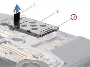
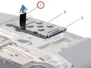
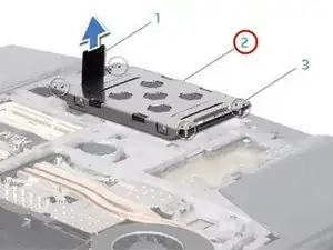
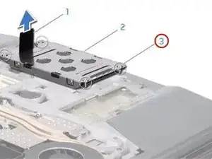
    • Loosen the four captive screws that secure the hard-drive assembly.

  15. dHabVlwiHuyaMGaj
    • Using the pull-tab, lift the hard-drive assembly out of the hard-drive bay.

  16. gICiMe3SXDqAwueS
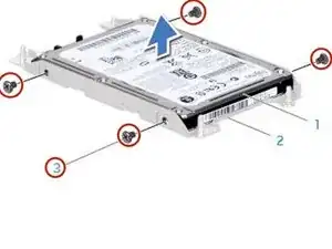
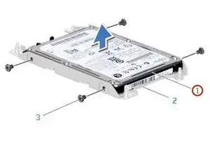
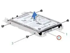
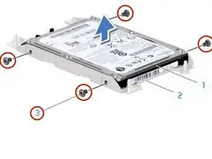
    • Remove the four screws that secure the hard drive to the hard-drive bracket.

  17. xjqcSkxAmCImQti1
    xjqcSkxAmCImQti1
    xvmUNakhZrWtpxLw
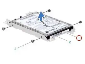
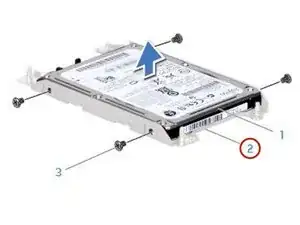
    • Lift the hard drive out of the hard-drive bracket.

  18. Jo5jjvXWDaOQS1IX
    Jo5jjvXWDaOQS1IX
    3smkYBkLqGEb6JrD
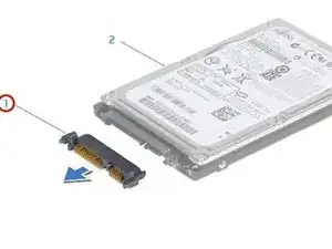
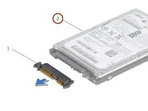
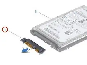
    • Disconnect the interposer from the hard drive.

  19. meEhTueZOw6vkDgV
    meEhTueZOw6vkDgV
    vleAnO3r1XL3HuQX
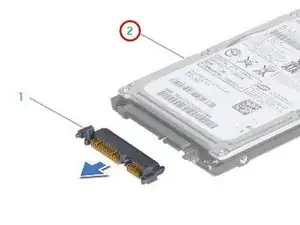
    • Connect the interposer to the NEW hard drive.

  20. VANQUSiBkwxVLXdi
    VANQUSiBkwxVLXdi
    FQlbHJZstXPCAu1A
    • Place the hard drive in the hard-drive bracket.

  21. 4QKCiQsXAUelAMAP
    • Replace the four screws that secure the hard drive to the hard-drive bracket.

  22. eAGRG1TrQScXhOJ3
    • Place the hard-drive assembly in the hard-drive bay.

  23. hyRopGWGhGTYbFRs
    • Align and tighten the four captive screws that secure the hard-drive assembly to the hard-drive bay.

  24. KjGZ2UVRjUTfDVPB
    • WARNING: Before working inside your computer, read the safety information that shipped with your computer.

    • CAUTION: To avoid electrostatic discharge, ground yourself by using a wrist grounding strap or by periodically touching an unpainted metal surface (such as a connector on the back of the computer).

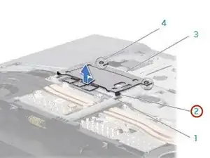
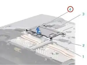
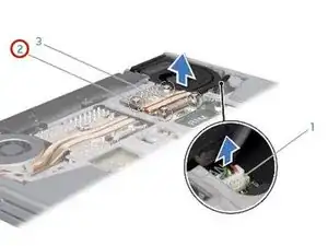
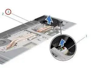
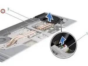
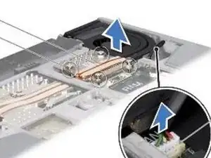
    • Disconnect the processor fan and heat sink assembly cable from the system board connector.

  25. kBkpcBUjsyLPimjQ
    • In sequential order (indicated on the processor fan and heat sink assembly), loosen the four captive screws that secure the processor fan and heat sink assembly to the system board.

  26. QFfMMYZE3ryr3gFO
    • Lift the processor fan and heat sink assembly off the system board.

    • Peel the backing off the thermal cooling pads attached to the NEW processor fan and heat sink assembly.

    • NOTE: If the processor fan and heat sink assembly is replaced, the thermal cooling pads will be attached to the new processor fan and heat sink assembly. Do not reuse the old thermal cooling pads.

  27. koenqLgLp2624LNj
    • Align the four captive screws on the processor heat sink with the screw holes on the system board and tighten the screws in sequential order (indicated on the processor fan and heat sink assembly).

  28. W46nRQ2Jdc6dyq2P
    • Tighten the screw that secures the processor fan and heat sink assembly to the computer base.

  29. IeH5J3pc3FgLfmCO
    • Connect the processor fan and heat sink assembly cable to the system board connector.

Abschluss

To reassemble your device, follow these instructions in reverse order.
Terrence15

Mitglied seit: 18/12/17

78652 Reputation

0 Kommentare