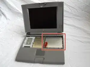
Einleitung

This repair will need:

A T-8 or T-6 Torx Screwdriver.

  1. D1g5KMDYN2DAfNaP
    D1g5KMDYN2DAfNaP
    wWaZIW4cUHx3Zmmb
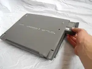
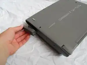
    • Turn computer over.

    • Remove battery expansion cover and battery.

  2. rLGDmJFQxcdigEeJ
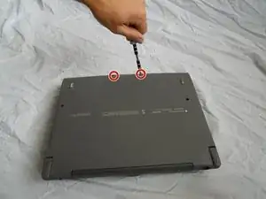
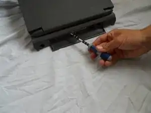
    • With monitor hinge at the bottom, remove the two top center screws.

    Not necessary for RAM, hard drive, or CPU replacement.

    Miles Raymond -

    The Screws are T8!

    Willy Kaiser -

  3. twOUoWexsXlW1uVP
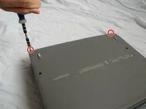
    • Remove top left and top right screws.

    Also not necessary for RAM, hard drive, or CPU replacement.

    Miles Raymond -

  4. byvSMiLHJHFfeIJr
    • Remove middle left and middle right screws.

  5. Ri1GUqQGUvurgVT1
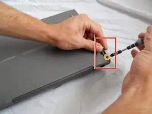
    • Open computer kickstands.

    • Remove screws underneath each kickstand.

    Again not necessary for RAM, hard drive, or CPU replacement.

    Miles Raymond -

    Philips PH00 screws

    8-Bit Hero Wendler -

  6. gR3sumUuXvQdPVVe
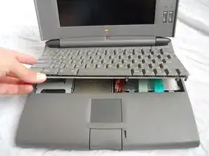
    • Lift keyboard from bottom and take out of shell.

  7. hRJhC1ijLUeeUE6T
    hRJhC1ijLUeeUE6T
    US4iUZZyhPrNmMCE
    GapU6CkPmNcDl6P1
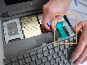
    • Lift the white ribbon clamps securing the keyboard ribbon cables to the motherboard. You can do this using a plastic opening tool.

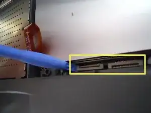
    • Removing both ribbon cables from the motherboard will leave the clamps like so.

    • From here you can access the logic board, hard drive, and floppy drive.

  8. VtiCAJ1lr3WxOUoP
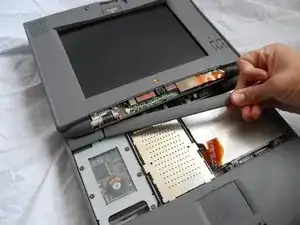
    • Remove the plastic panel on the bottom of the LCD Screen.

    Not necessary for RAM, hard drive, or CPU replacement. This may also cause excess wear on the already-fragile plastic pieces that hold it in.

    Miles Raymond -

  9. 2sc44B2BYcUvMAY2
    • Open panel on back of the device. Remove 2 T8 torque screws.

  10. SFbuahIKRkSCU6FT
    • Remove the plastic panel underneath the LCD Screen.

  11. McapDDrBPJblyRIJ
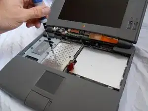
    • Remove the 2 T8 Torx Screws securing the logic board protection plate from the midsection of the logic board protection plate. Remove the T8 Torx Screw from the back of the plate, underneath the hinge.

  12. RgKFTXGM1Z6KtISg
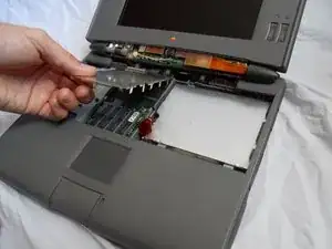
    • Remove the logic board protection plate.

  13. MdR6erOeuSBVhVYN
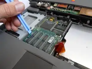
    • Using a plastic spudger, gently pry up the uppermost board fixture. This is the Memory (RAM).

    Beware: there might be a little plastic 'bridge' piece that goes around the memory connector (mine had one that isn't in this guide) which needs to be removed first before removing the RAM card. It was both difficult to remove and fragile (broke on one side during removal).

    Miles Raymond -

  14. PpvqYABF5EZXDiNw
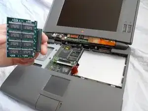
    • Once the old Memory board is removed, replace it with the new Memory board.

Abschluss

To reassemble your device, follow these instructions in reverse order.
Tyler

Mitglied seit: 10/04/11

138 Reputation

0 Kommentare