Einleitung
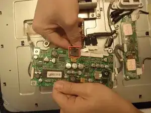
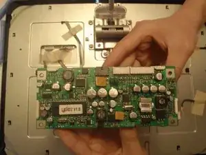
The LCD main board is the backbone of the Apple Studio Display M2454. It accepts the information coming from the computer and transmits this data to the screen to form an image. The main board is also wired into the USB ports on the back of the monitor and other circuitry. There are many connections but replacing this board is relatively easy.
Werkzeuge
-
-
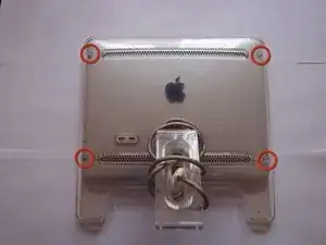
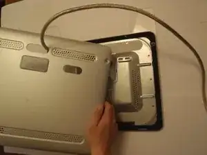
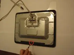
Locate the four hex head screws located on the corners of the back panel.
-
Remove the screws with a 2mm hex screwdriver.
-
-
-
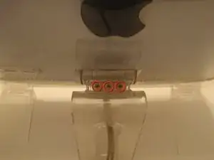
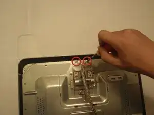
Locate the three 2mm hex screws located on the back stand of the monitor.
-
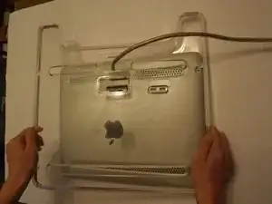
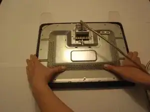
These screws must be removed with the 2mm hex screwdriver in order for the back panel to be removed.
-
-
-
Remove the phillips head screw holding the back panel spacer with the phillips head screwdriver.
-
-
-
Remove the two phillips head screws near the cable attachment with the phillips head screwdriver.
-
-
-
To remove the metal plate covering the circuitry you need to push the cover towards the base of the monitor.
-
If done correctly the tabs holding the plate should be detached and the plate will easily pop off.
-
-
-
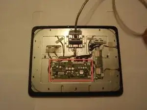
Now that the circuitry is exposed the boards can be seen and replaced.
-
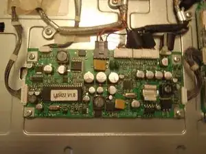
The LCD Main Board is the largest board in the center of the device with seven external connections.
-
-
-
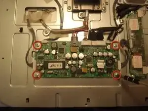
Locate the four phillips head screws on the corners of the board.
-
Using the phillips head screwdriver, remove the four screws holding the board to the monitor.
-
-
-
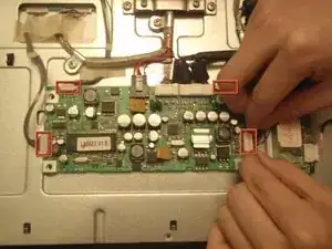
Remove the four braided connections simply by pushing the side of the connectors in and pull out.
-
-
-
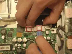
Remove the other two connectors by raising the tab on each either by hand or using a flat ended tool as shown.
-
Then gently pull away from the board to release tabs.
-
-
-
Remove the final black connector by pressing down on the back of the tab on the connector and then pull away from the board.
-
-
-
With all the connectors removed the board can be lifted away.
-
Now the new board can be attached by following the previous steps in reverse.
-
