Einleitung

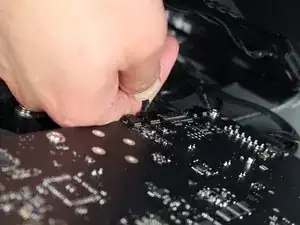
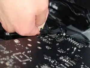
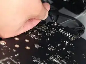
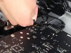
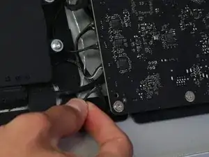
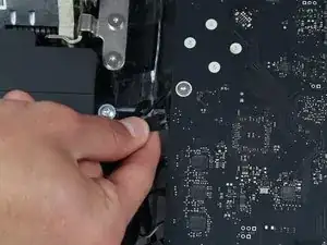
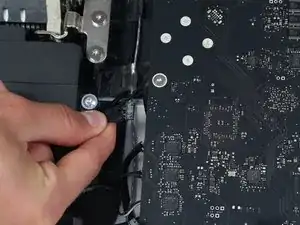
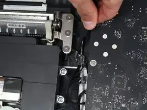
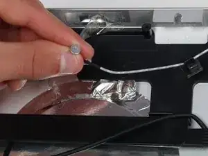
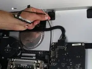
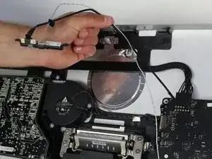
Nachdem das LCD entfernt ist, sieht es so aus, dass man die Webcam und das Mikrofon einfach erreicht. Mit dem Logic Board sind sie durch zwei Kabel verbunden, die hinter vielen anderen Kabeln liegen, was es etwas schwieriger macht, sie dort zu finden. Wenn man den Stecker des Mikrofons gefunden hat, benötigt man unbedingt eine Pinzette, um ihn zu entfernen!

  1. vKYkNXJG6EyYZXwb
    vKYkNXJG6EyYZXwb
    bdoSe25Kx2AEFnuf
    Fy6tFKoYcjhdx4uu
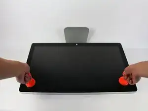
    • Lege das Display mit der Bildschirmseite nach oben ab.

    • Der Standfuß ist beweglich. Deswegen ist es gut, wenn du das Display mit einem Hartschaumblock gegen den Fuß abstützt.

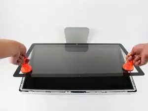
    • Bringe die Saugheber auf beiden Seiten oben fest am Bildschirm an.

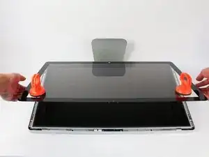
    • Die Glasscheibe ist am restlichen Bildschirm mit kleinen Magneten befestigt. Hebe langsam an, bis sie sich ablöst.

    Instead of $14 foam block, I used a full roll of paper towel and two pillows. While it worked, if I ever did this again, I would buy the block of foam. Since you’re removing a power cable, you need to be able thread it through and I think the foam block would make that easier.

    Josh Miller -

    You can also use a single handle, double cup floor lifting suction cup. Just place it in the centre of the screen near the camera and lift slowly.

    Steve A -

    I just used a toilet plunger to remove the screen and it worked like a charm!

    Philip Jacob -

    That’s what I call resourceful—made my day. I hope your repair was successful.

    Tobias Isakeit -

    Great idea, thanks a lot!

    Yvan Sandoz -

    The glass lifted off the magnets quite easily after just using my fingernails. No suction cups or toilet accessories needed.

    Adrian Gropper -

    I had the same problem and after removal of the fan and a bit of work with the vacuum, the fan is quiet. Thanks to ifixit for the great instructions that made this easy.

    John Perser -

    To keep the screen up, other soft objects might work, but it's important that the hole in the back isn't covered because you will need to thread the new Thunderbolt/MagSafe cable through it and it would be a hassle to do it after everything's been set up.

    Thomas -

    Anybody got any links to glass screen replacement supplier for the A1407 Thunderbolt Display? Im finding it impossible to find a replacement without it being crazy money.

    Michael McMillan -

    Instead of a wedge, I used 4 rolls of toiletpaper, one under each corner.

    jnbruin -

  2. y1QM4GJuH1vKrEUg
    y1QM4GJuH1vKrEUg
    xV1xJRpqEugIUYOL
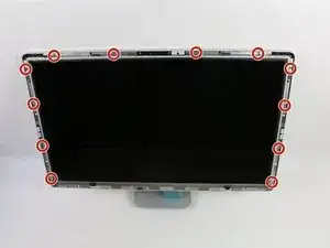
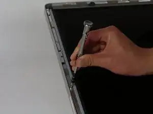
    • Drehe zwölf Torx TR10 Schrauben an der Oberkante und den Seitenkanten heraus.

    The screws marked in orange don't need to be removed, all they do is hold the magnets on the LCD.

    Garrett Mace -

    Yes “orange screws” does not need to be removed.

    You do not need a TR10 screwdriver as written in the text a T10 will suffice (more common and also correctly mentioned in the list of tools).

    A TR10 screwdriver is compatible with the T10, but not the other way around

    Per Lohmann Poulsen -

    On mine, the orange screws did hold the LCD down; the magnets were held in by TR6 screws, and those did not need to be removed.

    jml9904 -

  3. dNtDx1LZQDU1OVbo
    dNtDx1LZQDU1OVbo
    OSaiV2IVJO3u5HPx
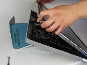
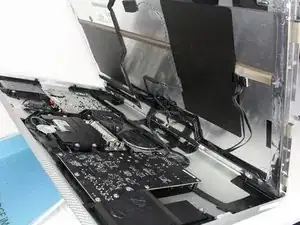
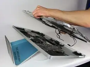
    • Hebe das Display langsam aus seinem Sitz heraus und kippe es hoch.

    • Es ist sehr hilfreich, wenn dich zwei weitere Hände unterstützen und das LCD festhalten, während du an den Kabeln darunter arbeitest.

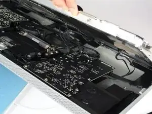
    • Das LCD ist mit vier Kabeln an den restlichen Bauteilen angeschlossen. Achte darauf, dass du nicht zu fest an ihnen ziehst und sie beschädigst.

    Add the note that it should be lifted from the bottom edge. It is also important not to twist the display by levering up from one corner.

    Charlie Nancarrow -

    Before lifting the monitor, you should be prepared to start collecting screws and have your TR 10 ready.

    Josh Miller -

    Having a couple of short screwdrivers handy to prop up the LCD (like you would a car hood) while you disconnect the cables helps.

    jml9904 -

  4. vYMImIhPgImDC4sZ
    vYMImIhPgImDC4sZ
    KwPHhIYJrH6vl4ZA
    ltsqwLZEIXOkvKZf
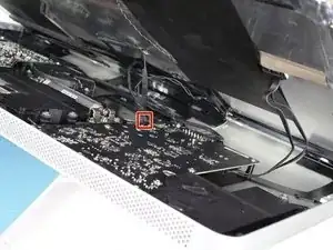
    • Fasse den Stecker des ersten Kabels (das, was am weitesten von dem mit Schrauben befestigten entfernt ist) an und ziehe ihn langsam heraus.

    Note: be sure to pull away but not hard. Wiggle and pull slowly. These are delicate especially due to age.

    Overall this is a moderate repair. Follow step by step and you are good.

    Also, use tape and/or labels to mark which cables go where per the MLB and other parts. Resulting in easier reassembly.

    Ted Teske -

  5. aJXhUDyuRDBEYIPX
    aJXhUDyuRDBEYIPX
    TvkYkf3pUBHBJZEQ
    N6oVUvAxqymMUFXn
    • Um an den Stecker vom nächsten Kabel, direkt neben dem eben gelösten, zu gelangen, musst du erst an einem Stück Klebeband an einer Metallleiste ziehen.

    • Benutze das Klebeband als Griff und klappe die Metallleiste herum.

    • Fasse dann den Stecker und ziehe ihn langsam aus dem Anschluss auf dem Logic Board ab.

    What is this connector for?

    pdspanagel -

    I imagine this connector is going to be for display data (i.e. LCD data).

    Scott Havard -

    I pretty much mangled this cable trying to put it back into the slot. Is this something I can order a replacement for?

    Ryan Stryker -

    I also screwed up this wire.

    erybovic -

    I also screwed up this wire. Wondering what the wire name is.

    erybovic -

    Thunderbolt Display 27" LVDS Cable

    Klaus Finke -

    As other’s have said, this cable is super delicate.

    When you replace it, make sure that the small metal handle it firmly reattached to the other side of the port. I thought I’d got it right first time, but had no video signal (thunderbolt detected display, and power was fed to the Macbook Pro).

    I had to reinsert this one again, and one in, firmly press the connector home, then latch the handle over the other side. I also gave it a test pull to ensure it was secure. Then all was well!

    Steve A -

    Managed to remove it but broke one pin putting it back. I don’t understand why they make so fragile with all the space available…

    BAULARD -

    Can anyone provide a photo of this connector so as to give a better understanding of its mechanics? see this cringe worthy effort at guidance; https://youtu.be/A96CUSm_Xhs?t=1050

    Philip Sharp -

  6. yYhUxvsdBk3pv3Io
    yYhUxvsdBk3pv3Io
    EyjpfRYE2bE1xGWk
    a4reZswHC1EsBc11
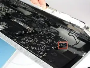
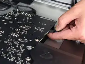
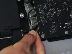
    • Fasse behutsam den Stecker auf der anderen Seite des Logic Boards unten an und ziehe ihn vom Board ab.

    To remove this connector, you squeeze the lower tab to unclasp it, and pull it sideways away from the board

    Brad Bell -

    This cable was also taped for me, so remove the tape first

    danmcfalls -

  7. sjOHkIKEoj3IwvE6
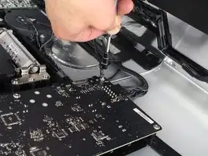
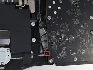
    • Das letzte Kabel des LCDs ist mit einer Torx T 10 Schraube gesichert. Drehe sie heraus.

  8. fGJtJg1gy2EQTqVl
    fGJtJg1gy2EQTqVl
    XNFyMYy5JtA3VvQX
    • Jetzt ist das LCD komplett vom Gehäuse abgetrennt. Du kannst es herausnehmen.

    • Lege das LCD am Besten auf ein Bett oder ein dickes Tuch um Schäden am LCD zu verhindern.

  9. 1VZLTCGYOoQ21IJ6
    1VZLTCGYOoQ21IJ6
    JneqgH4XrEKnCZUx
    pKfJI6VgYMZOmyQd
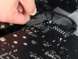
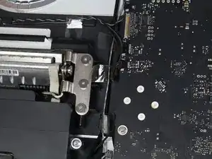
    • Die Webcam und das Mikrofon befinden sich oben am Gerät. Folge dem weißen Kabel nach unten bis zum Stecker auf dem Logic Board.

    • Ziehe den Stecker am weißen Kabel behutsam vom Logic Board ab.

  10. VUlfKubFDKFYpoKb
    VUlfKubFDKFYpoKb
    yGM3nyondKgVSyH1
    • Folge dem Webcam-Kabel bis zum Anschluss auf dem Logic Board.

    • Ziehe vorsichtig den Stecker vom Logic Board ab.

  11. JuEMwXxkjlC4Tw5V
    JuEMwXxkjlC4Tw5V
    MjOHALsE6ws4MrIH
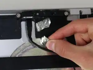
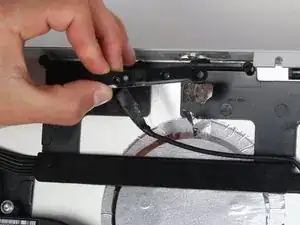
    • Die Kabel sind mit drei Stückchen Klebeband befestigt. Ziehe die Klebebänder ab, so dass die Kabel frei kommen.

    • Die Klebebänder lassen sich leicht abziehen, so richtig notwendig sind sie nicht.

  12. WmjQeMSHG2TOt511
    WmjQeMSHG2TOt511
    SSG15mmoldFDiMiF
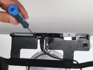
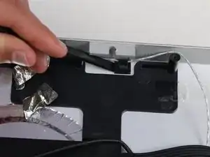
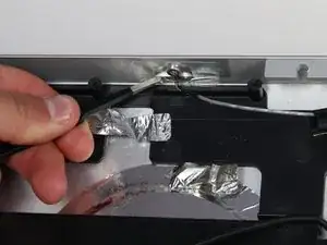
    • Oben am Gerät halten zwei Stücke silberfarbenes Klebeband die Webcam-Kabel fest.

    • Auch hier hilft eine Pinzette beim Ablösen der Klebebänder, es geht aber auch ohne.

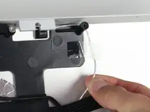
    • Als Nächstes wird das Klebeband am Mikrofon entfernt.

  13. KNgeN65ykZILswHB
    KNgeN65ykZILswHB
    lmc6lMmJ2dMVbxgr
    F4StWPB3tACg6rYm
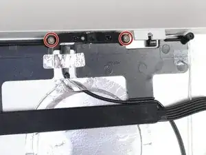
    • Die Webcam ist mit zwei Schrauben und einem Stecker befestigt.

    • Entferne die beiden Torx TR10 Schrauben.

    • Die Webcam ist frei.

  14. lnrBRMJrqt6pgF24
    lnrBRMJrqt6pgF24
    SJuPupFCx2X5ZCyN
    • Wenn die Webcam weg ist, wird das Mikrofon sichtbar.

    • Die Webcam ist mit einem Kunststoffclip befestigt, der mit Schaumkleber am Gehäuse verklebt ist.

    • Heble mit einem Spudger unter dem Clip und löse ihn vom Gehäuse ab.

    I have not done this repair yet, but from the images, think there’s a mistake in the instructions, and it should say, “The microphone is held in place with a plastic clip that has foam adhesive stuck to the casing.”

    Adam Scoville -

  15. m3yO4EswLwhcV2H4
    m3yO4EswLwhcV2H4
    YEtTP3MQB6BcE3Vm
    • Das Mikrofon selbst ist oben am Gerät ein wenig verklebt und mit einem Stück Klebeband bedeckt.

    • Um an das Mikrofon zu gelangen, musst du das Klebeband mit einer Pinzette oder den Fingern entfernen.

    • Heble mit dem Spudger unter dem kleinen runden Mikrofon und löse es aus der Klebeverbindung.

  16. UIepSlqpdGaDIU4b
    UIepSlqpdGaDIU4b
    6ZDvmD2aXfTYlbAO
    • Die Kabel zum Mikrofon und zur Webcam sind unter anderen Bauteilen durchgeführt.

    • Hole die Kabel vorsichtig unter den anderen Bauteilen heraus, dann kannst du das Mikrofon und die Kamera austauschen.

Abschluss

Arbeite die Schritte in umgekehrter Reihenfolge ab, um dein Gerät wieder zusammenzubauen.
Wesley Ho

Mitglied seit: 14/04/15

434 Reputation

0 Kommentare