Einleitung
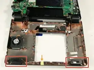
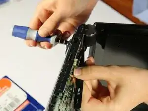
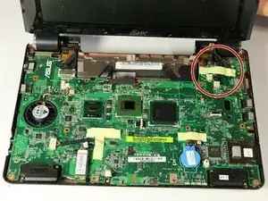
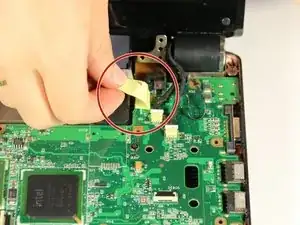
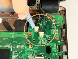
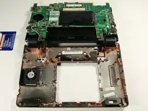
Follow this guide if you have determined that your speakers are the cause of your netbook's sound problem. The speakers are visible through a cutout in the motherboard, however the motherboard still must be removed to completely access and remove the speakers. This is due to the wire connecting the two speakers located underneath the motherboard. Similarly, the hard drive must be disconnected from the netbook to remove the motherboard, so it must be removed prior to removing the speaker.
Werkzeuge
-
-
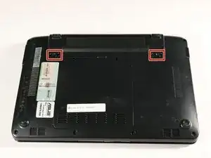
Lay the laptop down with the bottom facing upwards.
-
Locate the two battery lock slide tabs.
-
-
-
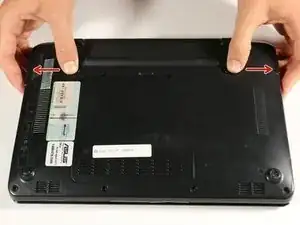
Slide the tabs outward to unlock the battery.
-
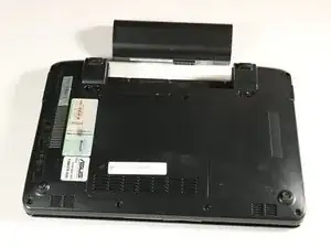
While holding the left tab outward, slide the battery away from you to remove it.
-
-
-
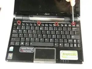
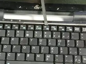
Identify the four connection points holding the top of the keyboard to the main body of the netbook. To remove the keyboard, use the spudger to unhook the keyboard upwards at these points.
-
-
-
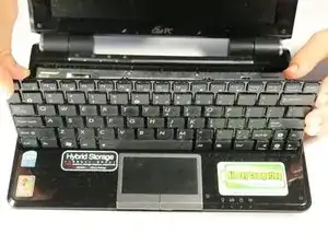
Flip the keyboard over by pulling the top edge of the keyboard away from the netbook body, using the bottom edge as a hinge point.
-
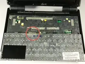
Locate the opaque strip, or ribbon cable, connecting the back of the keyboard to the hardware of the netbook.
-
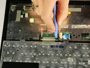
To disconnect the ribbon cable, use a plastic opening tool to pull each side of the black plastic strip, located below the ribbon cable, away from the ribbon cable.
-
The black strip will disconnect completely from the ribbon cable. The keyboard will then be detached from the netbook's body and can be safely removed.
-
-
-
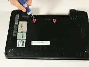
Using the Ph00 (+) Phillips screw head, unscrew the two 4 mm screws that hold the back panel in place.
-
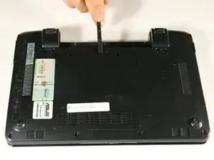
Use the spudger to gently pry off the back panel.
-
-
-
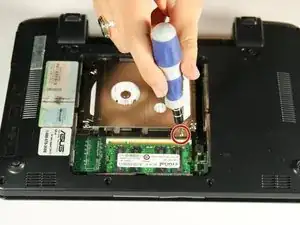
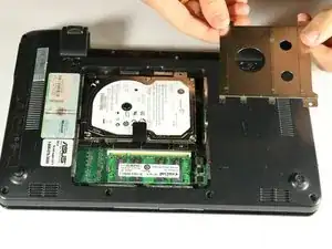
Use the PH00 (+) screw head and screw driver to remove the 4 mm screw holding down the hard drive cover.
-
-
-
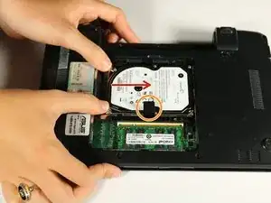
Slide the hard drive from the left towards the right side to detach it
-
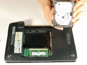
Once the hard drive is detached, lift the black tab and remove from the netbook.
-
-
-
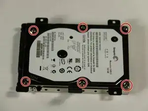
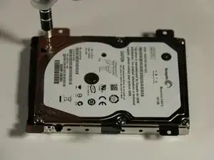
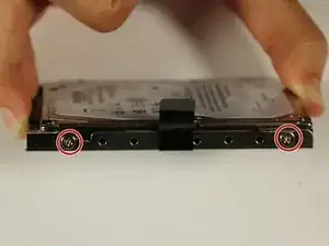
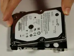
To remove the metal hard drive casing, use a T6 (star head) screwdriver head to remove six 4mm screws marked by the red circles in the picture.
-
-
-
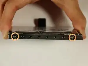
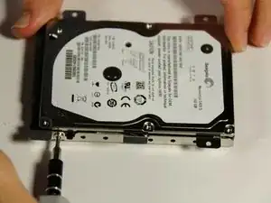
Next, remove the two 4mm screws on each side of the hard drive case shown by the blue circles. Use the PH00 (+) Philips head and screwdriver head used in the previous step to remove these 4 mm screws.
-
-
-
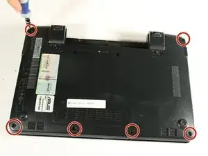
Orient your netbook so the back panel is facing up.
-
Locate the eight 7 mm screws on the edges of the back panels.
-
Remove these 7 mm screws using a PH00 (+) Philips head and screwdriver.
-
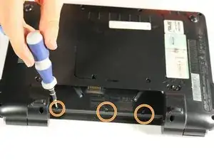
Orient the netbook so the battery compartment is closest to you.
-
Locate the three 7 mm screws on the back panel, beneath where the battery would be located before removal.
-
Remove the three 7 mm screws using a PH00 (+) Philips head and screwdriver.
-
-
-
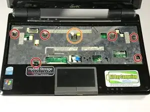
Orient the netbook the front panel is opened and the keyboard and screen are facing you (the orientation in which you would typically use the netbook).
-
Having already removed the keyboard, locate the six 7mm screws on the silver plate in the keyboard housing.
-
Remove the six 7 mm screws using a PH00 (+) Philips head and screwdriver.
-
If you choose to remove the sticker and void your netbook warranty, locate the yellow sticker and remove to reveal the seventh 7 mm screw.
-
Remove the seventh 7 mm screw with a PH00 (+) Philips head and screwdriver.
-
-
-
Locate the cord connected to the motherboard on the upper left and the ribbon strip connected to the motherboard on the bottom middle of the silver keyboard housing.
-
Remove the cord, on the upper left of the keyboard housing, from the connection point using the plastic opening tool. Place the plastic opening tool on one end of the white plastic piece. Pull on the edge of the piece to remove it from the connection housing.
-
Disconnect the ribbon from the connection housing by prying both ends of the cream plastic piece away from the ribbon.
-
-
-
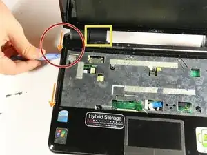
With the ribbons detached, you can now remove the front panel of the keyboard. The silver keyboard housing and the black piece are connected and make up the front panel.
-
Locate one back corner of the netbook near where the screen meets the body of the netbook.
-
Wedge the plastic opening tool between the two black layers of the netbook. There is a visible line that divides the bottom and top black pieces.
-
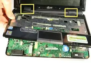
Run the plastic opening tool along the side of the netbook while lifting upwards, keeping it wedged between the two black pieces. This will loosen the connection.
-
Once the two pieces are loosened enough, you can place your fingers between the two pieces and lift the top piece off. The two inner black pieces of the hinge connection, between the screen and the netbook body, are attached to the front panel that you are removing.
-
-
-
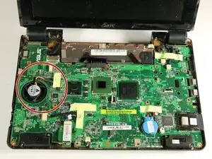
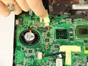
Locate the fan on the left side of the motherboard.
-
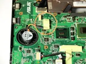
Locate the sticker next to the fan that is atop the fan connection cords.
-
Peel back the sticker.
-
-
-
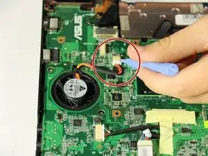
Locate the cord connected to the motherboard that is beneath the sticker that you peeled off in the previous step.
-
Use the plastic opening tool to remove the cords from the cream housing.
-
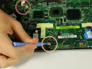
Locate the cord connected to the motherboard on the lower left.
-
Remove this cord using the plastic opening tool by prying the white plastic piece out from the cream housing.
-
-
-
To remove the motherboard from the netbook housing, you must detach it from the bottom black piece of the netbook.
-
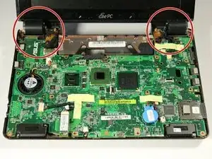
Locate the hinge points at the top of the netbook on each side. These pieces connect the screen to the netbook body.
-
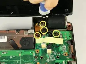
Locate three 7 mm screws to the right of the left hinge point in a vertical line.
-
Remove these 7 mm screws using a PH00 (+) Philips head and screwdriver.
-
Locate the four 7 mm screws to the left of the right hinge point.
-
Remove these 7 mm screws using the PH00 (+) Philips head and screwdriver.
-
-
-
For this step, orient the netbook with the screen folded down and the netbook flat on the ground with the back facing up. The battery compartment should be facing you.
-
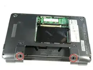
Locate the two 7 mm screws in the holes on either side of the battery compartment
-
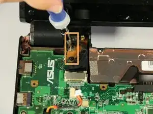
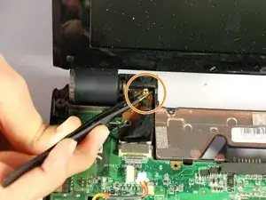
Opening up the computer screen, find the 3mm gold screw housing to the inside of each hinge point. These are next to the 7mm screws you removed in the previous step.
-
In this next step, you will remove the 7 mm screw from the side of the battery compartment while holding the gold 3 mm screw housing in place.
-
Position the netbook on its side. The side that is on the ground should not be the side that has the 7 mm screw you are trying to remove.
-
Hold the gold 3 mm screw housing in place using the black tweezers. Simultaneously remove the 7 mm screw on the side of the battery compartment, using the PH00 (+) Philips screwdriver head.
-
-
-
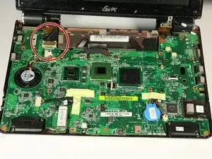
Orient the PC with the screen and motherboard towards you.
-
Peel back the tape holding down screen wires.
-
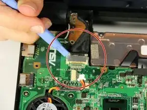
Detach white plastic wire bus connectors using the plastic opening tool.
-
-
-
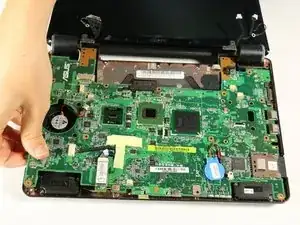
In order to detach the screen connector from the top left side of the motherboard you must peel back the tape holding down the fan wires.
-
Use the plastic opening tool to detach the cable from the motherboard.
-
-
-
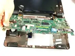
Use the plastic opening tool or your hand to carefully lift the left hand side of the motherboard away from the bottom plastic casing.
-
Lift and carefully pull out the motherboard to the left. The slots on the right side of the motherboard (for the USB and other connections) will pull free of the plastic housing when the motherboard is pulled to the left.
-
-
-
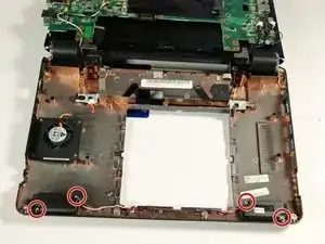
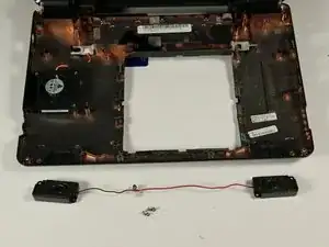
There are two speakers, one on the left and right side marked by the red boxes.
-
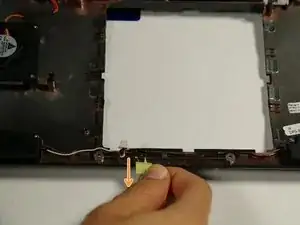
Pull back the tape covering the wires that run from both speakers marked by the blue arrow.
-
-
-
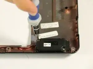
Remove the two 4mm screws from each speaker using a PH00 phillips head (+). The screws are marked by red circles.
-
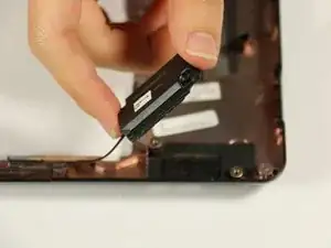
Lift the speakers out from the PC
-
To reassemble your device, follow these instructions in reverse order.
