Einleitung
This guide covers how to replace the Graphics Card for the Asus ROG G750JH-DB71.
The graphics card renders images on the screen. It uses the RAM to hold pictures and stores data of each pixel. Graphics cards have been getting better and better every generation, for some newer programs/games you will need a newer graphics card to run them.
-
-
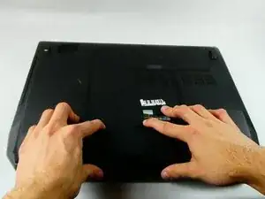
Push the switch near the front of the laptop to release the battery from the computer.
-
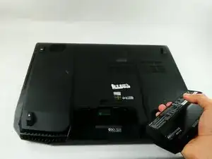
Pull the battery out and away from the center of the computer.
-
-
-
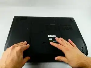
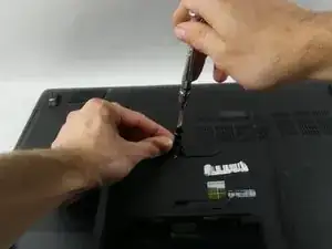
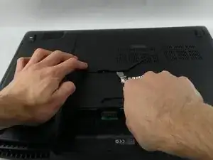
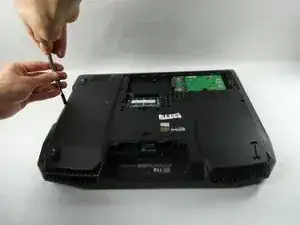
Use a spudger or your finger to lift up the plastic cover on back of the laptop.
-
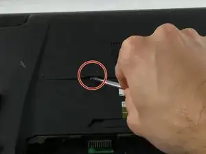
Under the plastic cover is a captive screw; unscrew it using a Phillips #00 screwdriver.
-
-
-
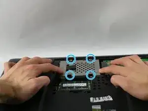
Remove the hard drive by unscrewing the 4.4 mm Phillips #00 screws.
-
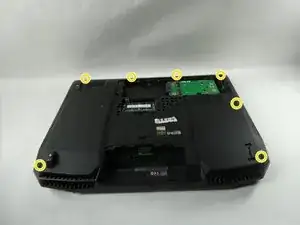
Remove all of the plastic caps around the edges using a pick or flathead screwdriver, and remove the screws underneath them. (one 13 mm Phillips #00, six 8 mm Phillips #00)
-
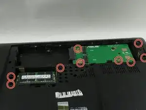
Remove all of the screws underneath the cover removed previously. (six 8mm Phillips #00, three 1 mm Phillips #00)
-
-
-
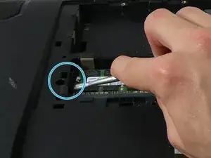
Push on the metal tab with a flathead screwdriver or an iFixit tool to remove the CD rom. It is located below a previously removed screw.
-
Remove the three (4 mm Phillips #00) screws that were previously covered by the CD rom.
-
-
-
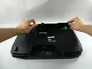
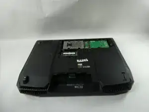
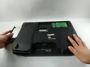
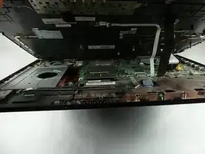
Once the screws are out and the CD rom is removed, the back cover can be taken off by hand.
-
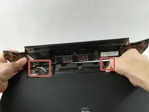
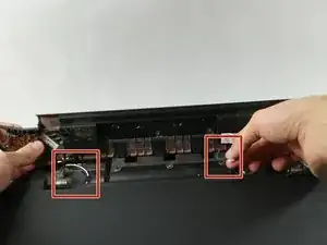
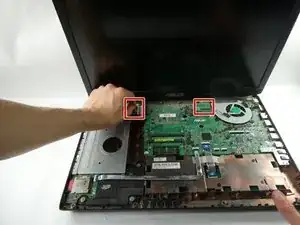
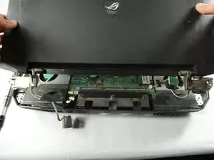
Disconnect the speaker cables located in picture 1 and 2.
-
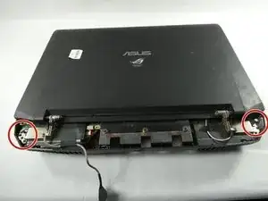
Remove two 8 mm Phillips #00 screws on each corner shown in picture 3.
-
-
-
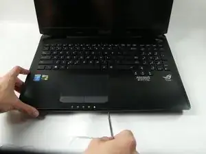
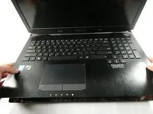
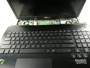
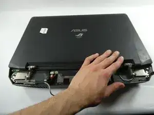
Now you can pull the keyboard off but make sure to do so carefully without damaging or scuffing any components.
-
Pull up and out at an angle as to avoid damaging the internals of the laptop.
-
-
-
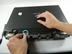
Slowly close the lid and turn the device around.
-
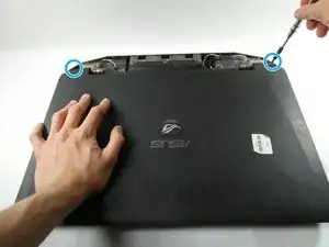
Remove the 6 screws (3 on each side) from the edges of the device. (8mm Phillips 00)
-
Remove the Webcam cable.
-
-
-
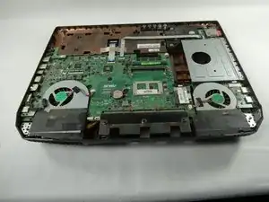
Remove the three screws surrounding each fan shown along with the ribbon cables connecting them to the motherboard. (4mm Phillips 00)
-
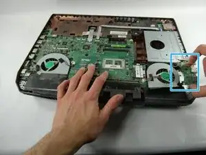
Remove the USB port board blocking the rightmost fan.
-
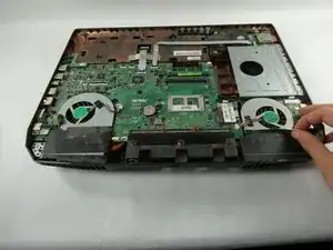
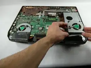
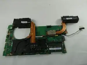
Remove the fans from the board.
-
-
-
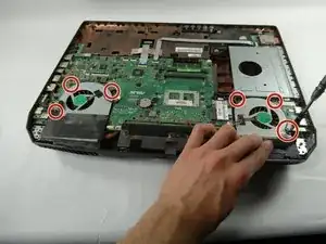
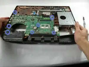
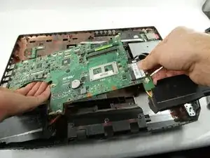
Remove all the screws connecting the motherboard to the case. (seven 4mm Phillips 00)
-
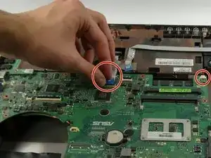
Remove the cables connecting to the main board.
-
-
-
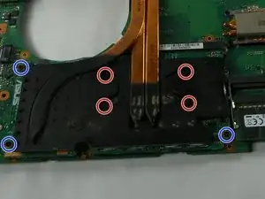
Remove the four screws connecting to the heat sink. (4mm Phillips 00)
-
Remove the 3 screws connected to the board. (1mm Phillips 00)
-
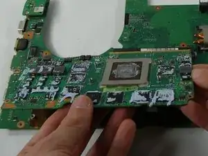
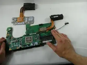
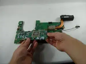
Lift the Graphics Card to remove it from the main board.
-

To reassemble your device, follow these instructions in reverse order.