Einleitung

The motherboard of the device is the tablet's main processing unit. To reach it, the plastic backing, battery, and camera must be removed.

  1. SOalTrHkInkOBLco
    SOalTrHkInkOBLco
    Z14gRYBwjwcLlvp6
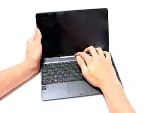
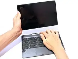
    • Separate the tablet from the base by pressing the large silver button below the tablet. The silver button is located at the base of the tablet.

    • Remove the tablet by lifting up.

  2. ZNtFFHEoPj4ZfWfK
    ZNtFFHEoPj4ZfWfK
    vqWrAMHZKBiPrLDp
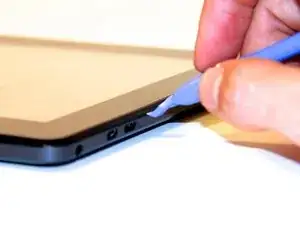
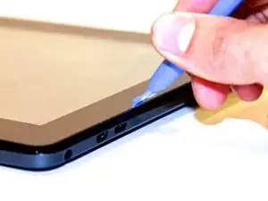
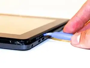
    • Insert the opening tool into the seam of the tablet casing and gently pry upwards.

    • With a little force, you will feel the clips release.

    This image seems not to show the correct position where to place the tip of the tool initially. It suggests to pry between the frame and the glass pane from the top of the tablet. That's what I did and broke the glass - one device spoilt. Only the next picture correctly shows where to apply the tool.

    Ole Hoppe -

  3. uxbNxZRywmlneFjN
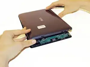
    • Slide the tool along all four edges of the tablet, making sure that all the clips are released.

    • Do not break these clips; otherwise, the screen will become less secure.

  4. AtnnGVcNQnXuU36H
    AtnnGVcNQnXuU36H
    XpCLQUWPvKX1o1Nd
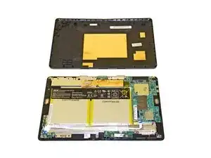
    • Remove the rear casing.

  5. YkKUfSfuWRSLPqPJ
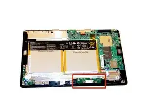
    • The camera board is located in the red square in this image.

  6. KgIUOBhK4QMLEgZE
    KgIUOBhK4QMLEgZE
    3u5RddOd2kKkfaEY
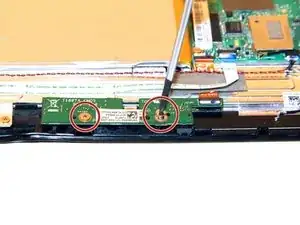
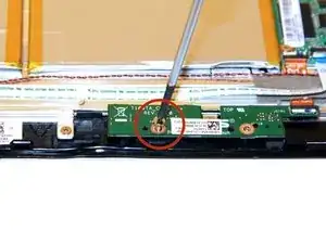
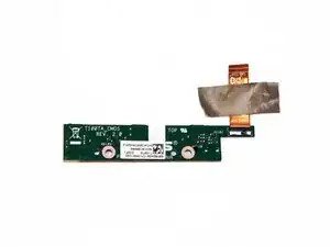
    • Remove the two screws on the camera board using a Phillips #1 Screwdriver.

  7. tCuZ5WVgVdAJMrPp
    tCuZ5WVgVdAJMrPp
    UKZcJVEpYtiYCouN
    e24BvQpHmnW2EtjM
    • Lift up the power button cable retention clip on the motherboard and pull the cable out.

    These "Connection Apparatuses" are ZIF (Zero Insertion Force) FFC (Flexible Flat Cable) Connectors, and instead of trying to pull/wiggle the ribbon cable out, the side of the Connector with the ribbon going into it, has a gate that will flip up making the ribbon just simply slide out. The ribbons are also easier to reinstall with the gates flipped up as well. You just have to be careful with the gates as to not break the hinges. I will typically use the plastic case opening tool to pry the gate open.

    Wingman -

  8. iAGMKHh1Kgbw6FRV
    iAGMKHh1Kgbw6FRV
    FgqTgLWjiJyxvUXW
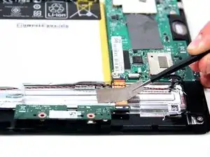
    • On the camera connection apparatus, locate the silver tape that connects to the tablet.

    • Peel the silver tape off of the tablet on both sides of the connection apparatus.

    • If this step has been completed correctly, the camera board should be loose, with the tape still attached to the connection apparatus.

  9. HeHkQiCd2qqW5GxP
    HeHkQiCd2qqW5GxP
    bEfNhdrMp1fkliUf
    WxFPVTmVyoRskkwj
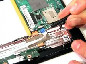
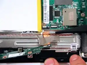
    • Gently pull the Orange ribbon cable out of the connection port.

    • This port has no clip. The orange apparatus should slide out with a small tug.

    This port DOES have a clip. It's the white bit on the backside of the port. Flip it up and the connector will slide loose with no force at all.

    blakebowen -

  10. KOfs53DdMvR5LHuA
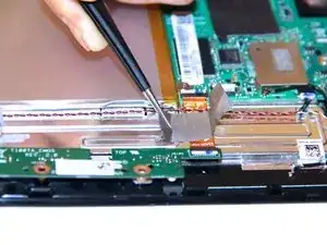
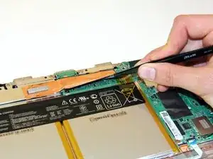
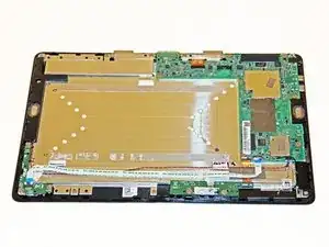
    • Remove the copper tape carefully.

  11. KPbVvAGvCUbFZtH5
    KPbVvAGvCUbFZtH5
    NkDqNhgIREcKYGpW
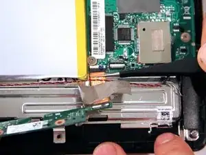
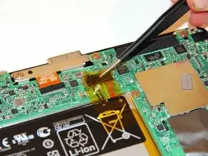
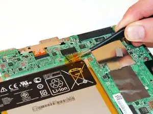
    • Gently pull back the yellow transparent plastic covering on top of the battery connection port.

  12. dIawDVgMTHgTtTCv
    dIawDVgMTHgTtTCv
    UUFxukMryP4Ed4ia
    kRXXWjGiAqMbryNq
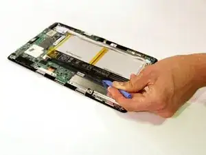
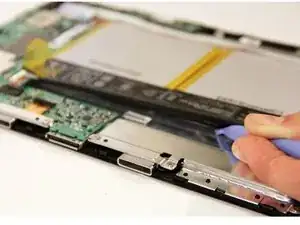
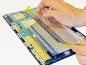
    • Rotate the device so the top of the screen is facing you. Place the plastic opening tool underneath the battery and gently pry upwards to lift the battery out.

    • The battery wire harness will slide out as the battery is pried up.

    My Asus Transformer is a T100TAF which doesn't have the yellow tape over the battery connector and the plug attached to the battery appears to be firmly fitted into the socket mounted on the Main Board. I have yet to work out how to remove the plug but the photo nearest above is a help as it shows the little spigot attached to the plug and which fits into the notch in the socket is in fact part of the plug. Back to the work bench.

    Keith Gooley -

    The battery plug was simply a very tight fit in the socket. My problem was the tablet not turning off properly when we wished. It would appear to switch off but was drawing about 250 mA from the battery which flattened it in a day or so. Unplugging the battery, waiting for a minute or so and re-connecting it solved the problem at least so far.

    Keith Gooley -

  13. aELZZAUoV1qqrCXV
    aELZZAUoV1qqrCXV
    QSucHHkQ6omkJZKL
    • Remove the battery by slowly peeling the battery away from the connected side.

    • The adhesive on the back will pull away from the battery.

  14. VZgyRnhI5nu2fyFl
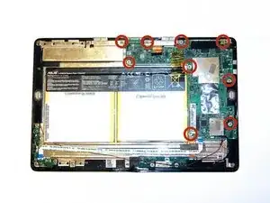
    • Remove the marked screws by using a Phillips #1 screwdriver.

  15. IxWIaKLDvHdfqTbT
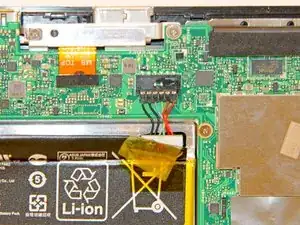
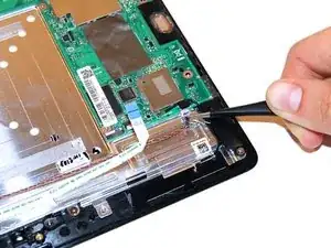
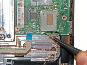
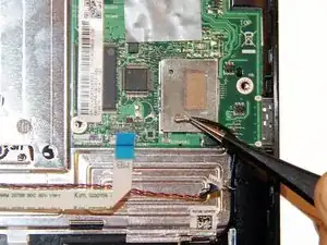
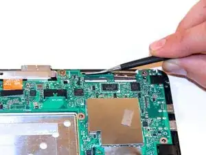
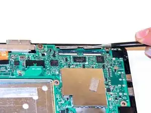
    • Locate the twisted black and red wire at the bottom of the motherboard.

    • Use tweezers to gently slide the black and red wire out of the connection port on the motherboard.

  16. BSOrEFma3jAmX3MQ
    BSOrEFma3jAmX3MQ
    rgSNuarnoKDggJjG
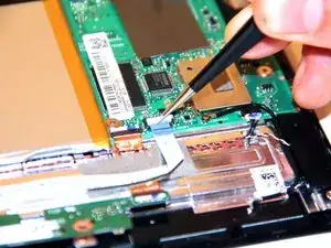
    • Next to the black and red wire, locate a black wire with a sliver connection ending.

    • Use tweezers to disconnect that wire from the motherboard

    • This wire disconnects in an upward motion, not in a sliding motion like the other connection ports.

  17. aaatfrScnwOkgTbD
    aaatfrScnwOkgTbD
    1pvlAAR6DTqtBgBZ
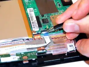
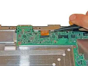
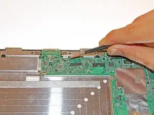
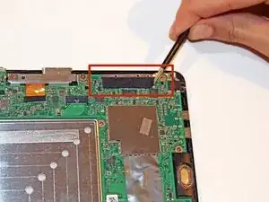
    • At the top end of the motherboard, use tweezers to gently slide the orange connection apparatus out of the connection port.

    Lift the white flap on the back of the connector before sliding the cable out.

    blakebowen -

  18. oZuZkDl2ud3qSNq6
    oZuZkDl2ud3qSNq6
    Yp3fGwUXC41T5DvC
    atNeM5AEmqhsourI
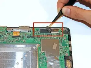
    • Next to the orange connection apparatus port, locate the LCD connection apparatus.

    • Use tweezers to peel the protective layer off of the connection port.

    • Be careful where the tweezers are placed. Make sure that only the squishy protective layer is being grabbed and peeled off.

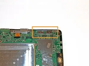
    • Once the tape is removed, the LCD connection port should look like this.

  19. lc4axBOuDxEQH5Bt
    lc4axBOuDxEQH5Bt
    UTIeUfcGuBxkMsMx
    cxAqcZVaMNnKMuW3
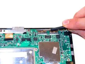
    • Using the tweezers, gently remove the LCD connection apparatus from the LCD connection port.

    • This can be tricky because the LCD connection apparatus has two sections. It is advised to gently wiggle one side out and then slide the second side out after.

    Lift both white flaps before removing the LCD connectors.

    blakebowen -

  20. 6TxKxpTLuqU62CKw
    6TxKxpTLuqU62CKw
    nHfKI4AIEMR3hVWy
    ayCMYvjNoVySoBtZ
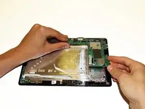
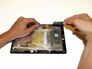
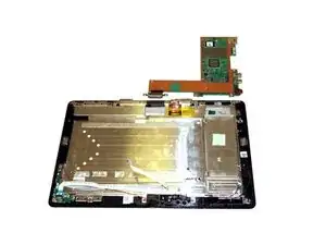
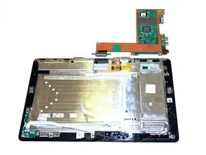
    • Using the top end of the motherboard as a hinge and fold the motherboard back so it rests outside of the tablet chassis.

    • There is a small amount of adhesive on the back side of the motherboard, which provides a small amount of resistance to the folding motion.

    • If done correctly, the motherboard should look the picture above.

Abschluss

To reassemble your device, follow these instructions in reverse order.

Taylor Pantiga

Mitglied seit: 14/04/14

1584 Reputation

11 Kommentare

As the previous comment stated (but only for step 7), ALL the connection apparatus have a white "flip" side (for STEP 7, 9, 17 and 19). Instead of struggling (like I did first), simply lift up the white side with your nail and gently remove the ribbons. Also, it is not necessary to entirely remove the battery (STEP 13) to carefully disconnect the cables. Thanks for for the tutorial though!

Brunilde -

Hey! I have the T100TA. Super happy with it, but it's a bit older and only has 1gb of RAM. Is it possible to put the board of the T100(which has 2gb of RAM) into it? I assume size is the same, but are the connections? Thanks!

Shayne Iles -

I have “downgraded” my T100TAM by installing a motherboard from the T100 (because I couldn’t find a T100TAM motherboard). So the other way around should also be possible.

Inspector Norse -

I replaced the motherboard. Did everthing right. But it didn't turned on.

Is there any way to start up the motherboard first time?
mauroabram -

Where is the hard drive located on these? Is it on the board and can it be swapped out? I have data on one which is locked and the device won’t boot to anything at all so stuck!
Scott spooner -

the problem of my t101ha is sdg smd in motherboard i cannot recall the value .. plsss help me

Rene Castro -

Thanks for the tutorial! I did not realize there is a tool for opening gadgets. I almost always break a few plastic clips. By replacing the motherboard of Asus T100 tablets is there a compatibility list I can use to buy a replacement? I have a T100TA-DK046H (~500$) from 2014, which has possibly motherboard issues (it does not recognize TPM and turns off randomly after showing some screen artifacts). It has a 90NB0451-R00100 motherboard. I got a quotation from a company for a new motherboard and repair, but it is a lot more than I expected (~300$) and I can see much cheaper (<100$) Asus motherboards on amazon and ebay e.g. 60NB0450-MB1012. I think I would rather buy something like that if it is compatible with the touch screen and other periferials and fix it myself…

László Lajos Jánszky -

I think all T100* mobo is compatible with all T100* periferials. At least that is my impression from post, comments and the reply of the Asus service.

László Lajos Jánszky -

what is wifi model?

volkan yıldırım -

Please note the T100TAF BING model has a different motherboard and no left speaker

Stephen Wornell -

I replaced the screen, damaged the original motherboard, then replaced it with a new motherboard. Unfortunately, now it wont start. The power LED blinks 5 times white when I press the power button.

Is it because the new motherboard does not have the proper BIOS (or something like that) installed? Or does the blinking means that there is still a damaged hardware component ?

Thanks

Samuel Brossard-Pellerin -