Einleitung

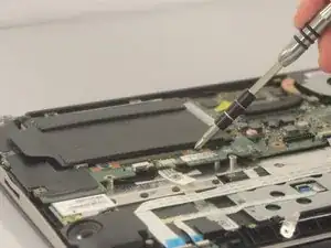
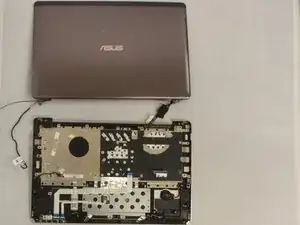
The display is used to display images sent to it by the motherboard. This guide will only show full display replacement, as the display is made of several parts glued together. However, to replace a component of the screen, the display must be removed in its entirety.

  1. LKdkrHB5TKeGVgfJ
    LKdkrHB5TKeGVgfJ
    P2oxK4mS2XhiJ5MF
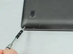
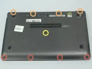
    • Flip the device such that the labels are on top.

    • Use a Phillips #1 screwdriver to remove the four 8mm screws near the back.

    • Use the same screwdriver to remove the four 5mm screws in the front.

    • Use the same screwdriver to remove the single 9mm screw in the center.

    • Make sure that the device is powered down and unplugged.

  2. Lnsq6IVhuTVMTSK1
    Lnsq6IVhuTVMTSK1
    k6qoSjjR2WXIeeam
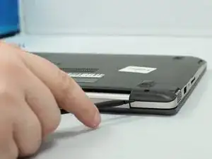
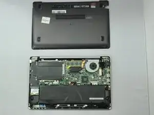
    • Remove the back cover by gently prying with a spudger.

  3. 3inPJ1SGTkaWDMkg
    3inPJ1SGTkaWDMkg
    kopYG66ha6P6XC6r
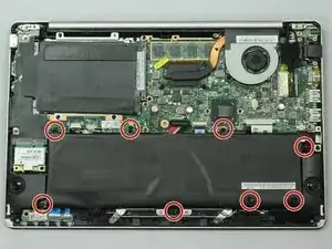
    • Remove the eight 5mm screws using a Phillips #1 screwdriver.

    • Do not puncture the battery.

  4. W6UoixvJyDs5gjEn
    • Disconnect the battery ribbon cable from the motherboard.

  5. d4SVFC6OBs6rZwZL
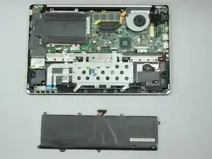
    • Remove the battery from the laptop.

  6. QqjSNdKJnThkUMly
    QqjSNdKJnThkUMly
    nPKZ1wG5GIumX1NQ
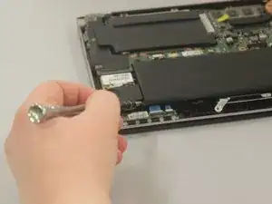
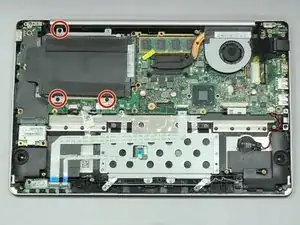
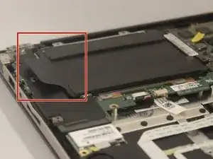
    • Unscrew the three 4mm screws holding the hard drive to the board.

  7. GXTgyR4uhb1XoIXA
    GXTgyR4uhb1XoIXA
    paYPePW2MfYPSVjC
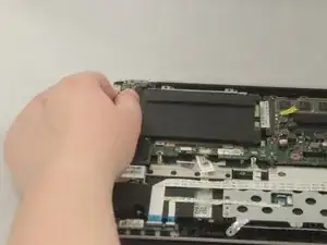
    • Pull on the tab on the left side of the hard drive and slowly disconnect it from the board.

  8. LmToD2d5eOa2oJZv
    LmToD2d5eOa2oJZv
    mmQFfjTSGVLrPKpX
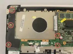
    • Unscrew the five 5mm screws holding the left board together.

  9. HJPX4OyDhph3oX6C
    HJPX4OyDhph3oX6C
    QROQE5PdnfhSeET2
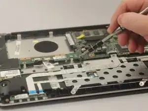
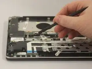
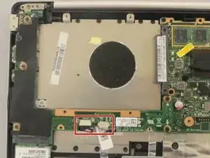
    • Unplug the two connectors on the left board.

  10. 4iSlPElElWlcdjUc
    4iSlPElElWlcdjUc
    kEBwWE3SLZqTYK4B
    wkwlfhNJ1xtX1G6P
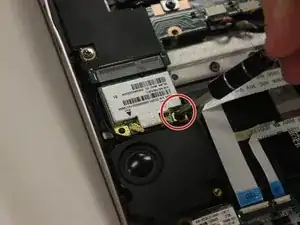
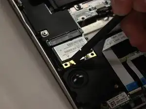
    • Remove the single 3mm screw from the sound chip.

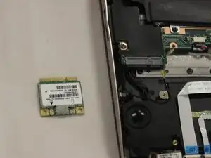
    • Unplug the sound chip.

    • Remove the sound chip.

    This is not the sound chip. this is the Wi-Fi Card attached here

    Joshua Guerra -

  11. kB2eaRHpVkOKM3bJ
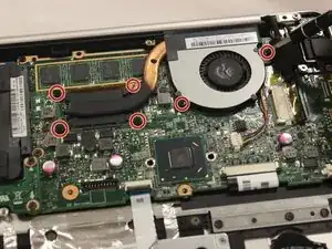
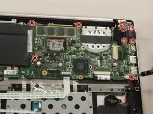
    • Remove the six 4mm screws holding the fan and CPU cover.

  12. YZFkn2dLDWDFF2LW
    YZFkn2dLDWDFF2LW
    6hMTGKBOZNkbkrkP
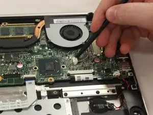
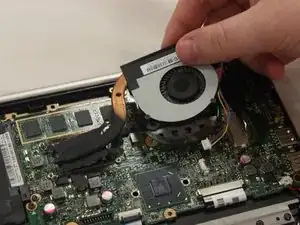
    • Unplug the fan.

    • Remove the fan and CPU cover.

  13. lsAs1fA3xhSV5BTA
    • Unscrew the nine 4mm screws holding the right board together.

  14. eVl3OqiIMjMKbgEp
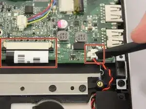
    • Remove the two remaining connectors on the board.

  15. GcsaZmyh4j1lknQj
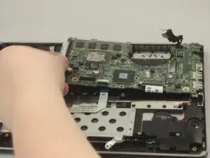
    • Remove the right board.

    Buena presentación,

    Me gustaría obtener un diagrama de la board, muchas gracias

    Ivan Riascos -

  16. IKtBGUffeHQEMFTL
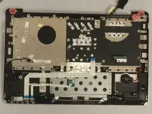
    • Unscrew the three 5mm screws holding the display to the main body of the computer.

  17. 6L1dM2GGledGXuwC
    6L1dM2GGledGXuwC
    FShAeKXOilYMDOyg
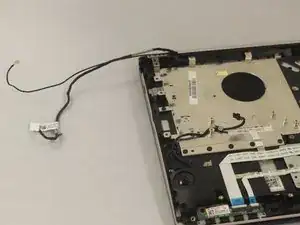
    • Unhook the cables coming from the display.

  18. FFPFpue4mwYRDl35
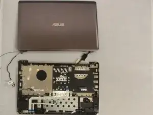
    • Tilt the screen away from the main body of the computer.

    • Remove the screen.

Abschluss

To reassemble your device, follow these instructions in reverse order.
John Thomas

Mitglied seit: 14/01/19

756 Reputation

0 Kommentare