Einleitung
This guide will show you how to replace the USB and HDMI Ports. Replacing these ports requires the removal of both the screen and the motherboard.
Werkzeuge
-
-
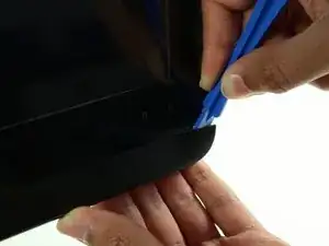
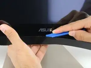
Use the plastic opening tool to pry off the black plastic strip at the bottom of the screen by wiggling the tool between the strip and the screen.
-
Run the opening tool slowly along the base of the screen, peeling the black strip back, until the opposite end of the screen is reached.
-
-
-
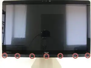
Use a Phillips #1 screwdriver to remove the seven (7) 4.8 mm screws from the base of the screen.
-
-
-
Place the computer on its back, facing up.
-
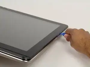
Wedge the plastic opening tool in between the screen and the bezel of the aluminum computer casing.
-
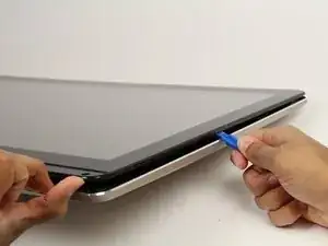
Move the tool along the entire edge of the screen with an up-and-down prying motion to loosen the screen from the casing. Do not lift the entire screen away from the computer yet.
-
-
-
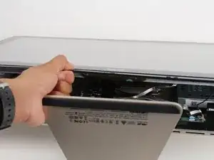
Lift the screen from the bottom edge by about 6 inches. Prop it open with one hand.
-
Look inside the computer and locate five (5) cables that connect the embedded components of the screen (camera, microphone, etc.) to the rest of the computer.
-
-
-
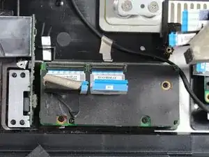
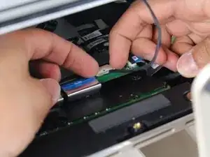
Remove the two (2) cables that are connected to the computer by white, rectangular terminal blocks by pulling straight out on the plug.
-
-
-
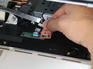
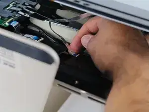
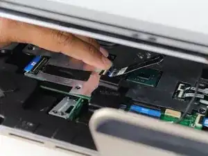
Use a finger to lift the plastic locking flaps that hold the remaining three (3) ribbon cables in place.
-
Remove the cables from their terminals by slipping them away from their connectors.
-
-
-
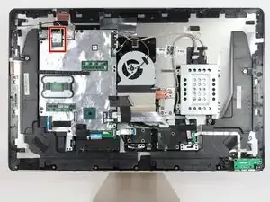
Locate the WLAN card in the upper left hand corner of the computer.
-
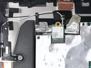
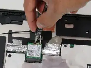
Use a Phillips #1 screwdriver to remove the 3.2 mm screw on the top of the WLAN card.
-
-
-
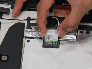
Pull out the WLAN card from its socket.
-
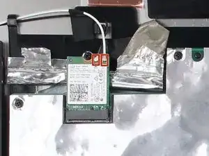
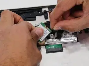
Remove the two antennae wires from the WLAN card by pulling up on the coaxial connectors.
-
-
-
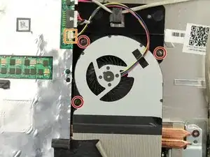
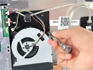
Use a Phillips #0 screwdriver to remove the three (3) 4.8 mm screws from the fan unit.
-
Remove the cable connecting the fan to the motherboard by pulling the cable out of its socket.
-
-
-
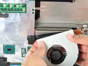
Remove the fan by peeling off the black electrical tape holding it against the heat sink vents.
-
-
-
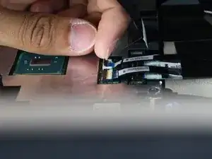
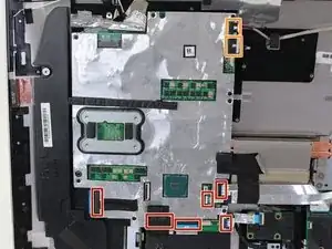
Remove the six (6) ribbon cables by lifting up on the plastic locking tabs and then slipping the cables out of their sockets.
-
Remove the other two (2) cables by pulling straight out on the white connectors.
-
-
-
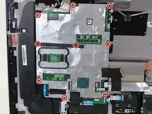
Use a Phillips #1 screwdriver to remove nine (9) 3.2 mm screws from the motherboard.
-
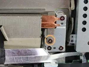
Use a Phillips #1 screwdriver to remove the one (1) 4.8 mm screw directly below the copper heat sink channel.
-
-
-
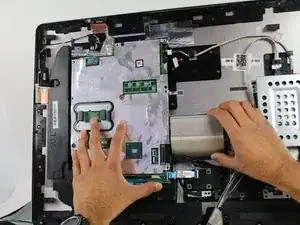
Lift the motherboard just enough to dismount it from the plastic pegs that hold it in place.
-
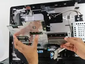
Rotate the motherboard towards yourself while supporting the heat sink by pivoting on its bottom edge.
-
-
-
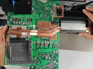
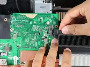
Remove the SATA cable on the opposite side of the motherboard by pulling directly up from the board.
-
-
-
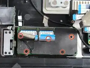
Use a Phillips #0 screwdriver to remove the five (5) 3.2 mm screws.
-
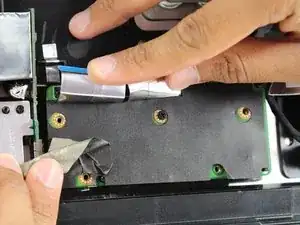
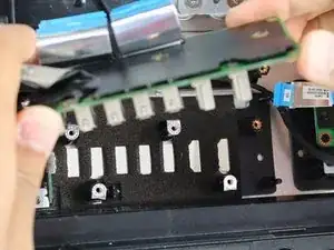
Remove the board by lifting it upwards.
-
To reassemble your device, follow these instructions in reverse order.
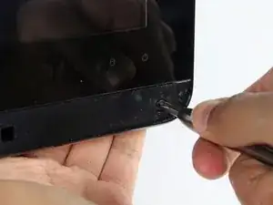
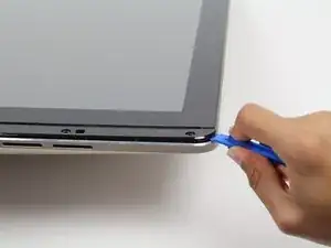

On my machine, it was positively impossible to use a plastic opening tool, or even a razor to get under the plastic strip - even after heating up with a heat gun. However, I found another method that will also help prevent damage to the plastic strip: in pictures for Steps 2 and 3, you can see that under the plastic strip, next to some of the screws there are square holes in the plastic body. I was able to shape a sturdy paper clip into an “L” shape, and feed it through the right-most exhaust vent at the bottom to insert into this square hole from below. From there, you can use the paper clip to try to push the plastic strip up from below. It still required some heat from the heat gun, but eventually I was able to push the plastic strip up enough to be able to slip a razor blade under it.
Alexander V Trofimuk -
I too was unable to do this with the plastic tools, but used a small flat screwdriver to ply up the corned on the bottom curved corner and plastic tools form there - just left a small blemish on the plastic besel, but I can live with that.
Andy Monaghan -