Einleitung
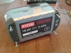
Diese Anleitung zeigt den Ausgleich der Zellenspannungen am Li-Ionen Akkupack der Ryobi One+ (130501002), das Prinzip gilt aber für alle Akkupacks. Es wird gezeigt, wie du den Pack öffnen kannst, die Zellenspannungen messen und, falls nötig, ausgleichen kannst.
An den Anschlüssen des Akkupacks solltest du 18V messen, maximal 21V. Wenn du Werte so um 12V hast, hat vermutlich eine Schutzelektronik angesprochen, weil die Zellen stark unterschiedliche Spannungen haben. (War bei mir jedenfalls so).
Ein Spannungausgleich ist möglicherweise hilfreich, wenn sich der Akkupack nicht mehr ganz aufladen lässt. (die Ladekontrollanzeige wird nicht mehr grün).
Die Schätzzeit für die Reparatur ist nur für das Öffnen und Messen. Die Ladezeit ist zusätzlich.
ACHTUNG! Offene Akkuzellen können hohe Ströme fließen lassen, sei vorsichtig!
Dieser Akkupack ist 2P5S konfiguriert, das heißt je zwei Zellen sind parallel, fünf dieser Paare sind seriell geschaltet. Hier wurden Sanyo 18650 Li-Ionen Zellen verwendet.
Werkzeuge
-
-
ACHTUNG! Offene Akkuzellen können hohe Ströme fließen lassen. Sei vorsichtig.
-
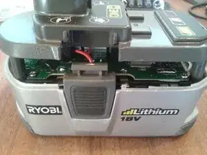
Entferne die vier Torx T15 Sicherheitsschrauben am Boden.
-
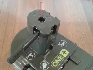
Entferne die einzelne Torx T10 Schraube an der Oberseite.
-
-
-
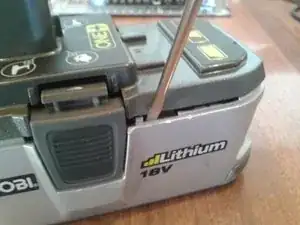
Drücke die Rasten weg, so dass die Oberseite frei wird. Heble nach oben, so dass das Unterteil abspringt.
-
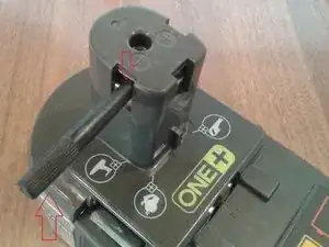
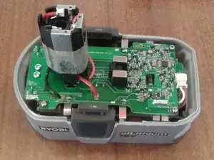
Drücke mit einem isolierten Werkzeug die Akkuanschlusseinheit im Innern des Oberteils nach unten.
-
ACHTUNG! Benutze für diesen Schritt kein Metallwerkzeug, du riskierst sonst einen Kurzschluss.
-
-
-
Wenn der Spalt groß genug ist, dann greife in das Innere hinein, halte die Akkuanschlusseinheit fest und ziehe das Oberteil nach oben ab.
-
Die Rasten für den Akkupack an den Seiten können entfernt werden, wenn du willst.
-
-
-
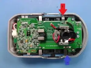
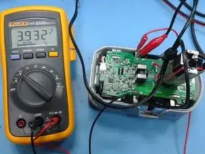
Jetzt kannst du mit einem Spannungsmesser (Multimeter auf DC Volt, Messbereich 10V) die verschiedenen Zellspannungen messen. Schreibe dir die Spannungen auf.
-
Zelle 1: zwischen TP1 und CL1
-
Zelle 2: zwischen CL1 und CL2
-
Zelle 3: zwischen CL2 und CL3
-
Zelle 4: zwischen CL3 und CL4
-
Zelle 5: zwischen CL4 und CL5 (Positiver Anschluss des Akkupacks)
-
Die gemessenen Werte sollten zwischen 3,0V und 4,2V liegen. Alle Zellen sollten den gleichen Wert haben, sagen wir 3,9V. Wenn sich die Zellenspannungen um mehr als 0,1V unterscheiden, dann kann diese Ungleichheit das Problem deines Akkupacks sein.
-
-
-
Du benötigt jetzt ein Labornetzteil mit einstellbarer Spannung und einstellbarer Strombegrenzung, dazu einen Strom- und Spannungsmesser. Stelle die Spannung auf den höchsten gemessenen Wert ein, die Strombegrenzung auf 0,5A.
-
Schließe das Netzteil an die Zelle an, die eine höhere Spannung erhalten soll, plus an plus, minus an minus. Das geht gut mit Krokodilklemmen.
-
Während des Aufladens steigt die Spannung an der Zelle bis zum vorgewählten Wert an, der Ladestrom geht auf Null zurück. Bei Null ist die Zelle aufgeladen.
-
Entferne das Netzteil und wiederhole die Spannungsmessung en.
-
Wiederhole das Verfahren solange, bis sich die Zellen höchstens um 0,1V unterscheiden.
-
Um dein Gerät wieder zusammenzusetzen, folge den Schritten ab Schritt 3 in umgekehrter Reihenfolge.
55 Kommentare
Using this guide, I successfully dismantled my 18V Ryobi Li-Ion battery with no problem. THANKS edwardb! In my case, I do have cell voltage imbalance exceeding 0.1V (3.48 to 3.36V). I would like to get your feedback on an alternate STEP 5 since I don't have a variable power supply yet. It seems that we recharging the individual pairs of SANYO cells to the same voltage so that the protection circuit will function properly again and allow the reassembled Ryobi battery to be recharged again using the standard Ryobi chargers. If this is this correct, then there might be 2 other options for reducing the cell imbalance to less than 0.1V as mentioned in STEP 5.
OPTION 1: Carefully deplete the cells having the higher voltage to reduce the voltage imbalance to less than 0.1V, or
OPTION 2: Carefully charge the lower voltage cells using a solar panel that has a power rating of less than 4.2Vx0.5amps =2 watts.
Would either OPTION 1 or 2 work?
Hi Al, Glad the guide is useful.
Yes your option 1 or option 2 would both work.
For option 1, use a power resistor with sufficient rating (say 10 ohm, 2W). Careful monitoring would be needed. Be sure to stay above 3.0V.
Option 2 should work fine too, might take a while depending on how many cells you can charge while the sun is out (and giving you good power in the solar panel).
Good luck
Ed
edwardb -
Ed, thanks for your quick response. This is how I re-balanced my cells. I charged the 4 lowest voltage cell pairs, one at a time, to the same level as the highest voltage cell (3.48V) using a spare 18V Ryobi battery. I connected one cell tab to one terminal of the spare Ryobi using thin bell wire (it's like speaker wire). The polarity is critical (negative-to-negative, or positive-to-positive). I then attached one end of another bell wire to the other terminal of the spare Ryobi. With the free end, I made frequent intermittent contact with the other cell tab. This means touching the wire to the cell tab long enough to see sparks and repeat the contact every 5-10 seconds, depending on how fast the wire heats up. If the wire is hot, then increase the interval between sparking. During this procedure, it is important to monitor the voltage across the cell. In less than a half hour, all cells were charged. After reassembly, I was able to charge the battery up to about 19.8V, a bit less than usual (20.5V). Amazing!
How about another alternative: why not use one of the higher voltage cells to charge one of the lower voltage cells? Put two of the cells together with a resistor or series of resistors in between them.
If my EE skills are in tact, you could put a chain of 470 milliOhm 1/4W resistors in series - one for every .1V difference. As the voltage difference drops, remove a resistor from the chain until there is only 1 resistor between the two cells that differ by .1V.
So for example, if one cell was 4.2 V and another was 3.6 V, put 6 of the resistors in series. When they go to 4.2 and 3.7 remove a resistor, when they go to 4.1 and 3.7 remove a resistor until one is 3.9 and the other is 3.8.
Mouser sells these resistors for less than 20 cents here: http://www.mouser.com/ProductDetail/Yage...
Your thoughts?
Kenton -
Kenton, you need to consider your application from the energy perspective. Cells in a Ryobi battery are normally cycled from 3.5 to 4.1V, resulting in 4.8 Wh output/cell. In your example, the 4.1V cell would lose about 1Wh of energy while discharging to 3.9V, based on what I’ve read on the internet. That energy would be distributed to a) the charging of the weaker cell, b) the heat load of your resistors, and c) the charging inefficiencies. For item a), the weaker cell would need about 2Wh charging from 3.6 to 3.8V. For item b), the resistors would dissipate <0.1Wh in one hour at say 0.3 amps. For item c), I would not be surprised if it takes an extra Wh to charge an cell by 2Wh. At the end of the day, you would likely have 2 depleted cells.
Ed’s original intent was to rebalance the cells without removing them from the Ryobi battery. For your approach, you would need to remove the cells if both the stronger and weaker cells come from the same battery pack. Hope this helps. What do you think Ed?
