Einleitung

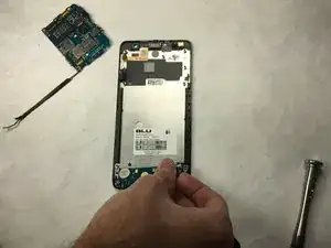
This guide will guide you through the steps required to replace the screen of a BLU Studio 5.0 S II. This guide will require difficulty the same as replacing the motherboard. The prerequisites will be everything for replacing the motherboard.

  1. BVU3ChSUdXFbWaRh
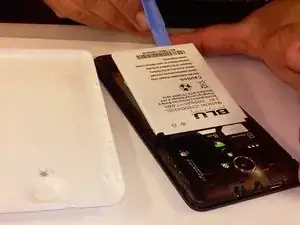
    • Remove the back cover of the phone with the plastic opening tool, or your fingers.

  2. DyJGojEoNIfqsTO3
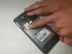
    • Remove the battery from the phone with the plastic opening tool, or your fingers.

  3. xlrDJTumCJTDpaFB
    xlrDJTumCJTDpaFB
    suxOTKGP5B1cVCXF
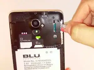
    • Remove the microSD and SIM card. Gently tug on the microSD and SIM card to slide them out of their insert.

  4. aClReeyMUPYXGAFS
    aClReeyMUPYXGAFS
    IPaVDF4d3tRwSs1o
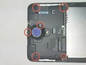
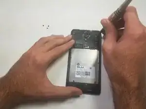
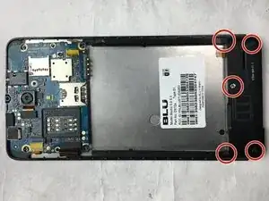
    • Locate the 5 black 3.5mm screws and the 1 3.5mm silver screw on the top back plate.

    • Remove the 6 3.5mm screws by using a Phillips #00 screwdriver.

  5. KevjDUrxrLirNwPR
    KevjDUrxrLirNwPR
    fCMxOELpPgXCFw3g
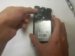
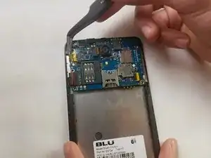
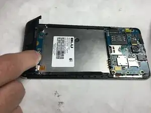
    • Remove the inner top back black plate.

  6. Fwf2NmQCv5WSaKDL
    Fwf2NmQCv5WSaKDL
    XFVJP5eoOIREjyKc
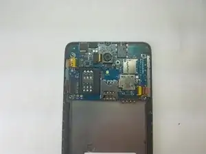
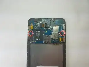
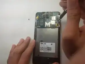
    • Locate the 2 black 3.5mm screws on the motherboard.

    • Remove the black 3.5 mm screws using a Phillips #00 screwdriver.

  7. rxkfsS2QlrrW1KPs
    rxkfsS2QlrrW1KPs
    AZAkQkklUudfkJVD
    XUeJdciaJglhQylM
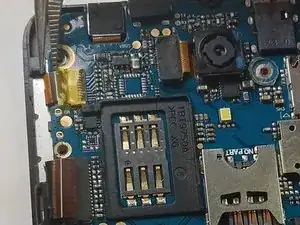
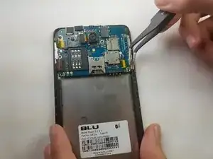
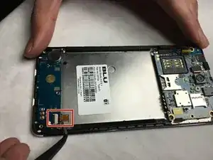
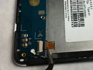
    • Locate the 2 orange ribbons on opposite sides.

    • Carefully remove the two ribbon cables using tweezers.

    • Gently rock the cable back and forth equally from both sides to not damage the pins.

  8. 5wnpg6feYHNZZvLZ
    5wnpg6feYHNZZvLZ
    PdM2F2t2WqBnvGY4
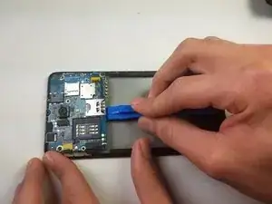
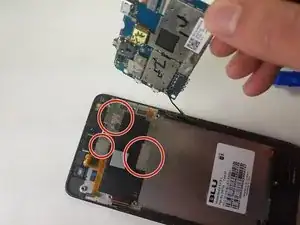
    • Gently rock the plastic opening tool back and forth until the motherboard releases from the phone.

    • Adhesion, identified with red circles, bonds the motherboard to the chassis. This may require extra effort to lift off from back of phone.

  9. ik2X2YMbufUc12Uc
    ik2X2YMbufUc12Uc
    Z3J1d2NVvlKPxLFm
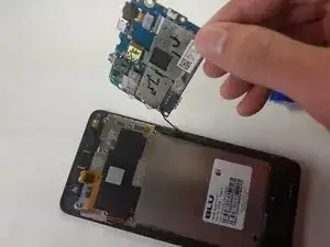
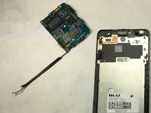
    • Follow the wire from the motherboard.

    • Remove the black lining covering the wire.

  10. sKkkEqGhSqraovtX
    sKkkEqGhSqraovtX
    2g53g2PB2mBDpGWG
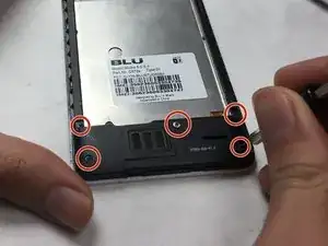
    • Locate the 5 black screws on inner black lower plate.

    • Remove the black 3.5 mm screws using a Phillips #00 screwdriver.

  11. ZLMCKf3oPMmadGp4
    ZLMCKf3oPMmadGp4
    sXDddKXsLyr3F6mU
    • Remove the bottom inner back plate.

  12. dBBcehOpWOLOO1bB
    dBBcehOpWOLOO1bB
    Ey6HYhonOxEuOMD4
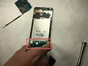
    • Holding the cable with the removal tool, gently pull in the direction of the cable to remove the connector from its socket.

    • Gently rock the cable back and forth equally from both sides to not damage the pins.

  13. FajRfW5gf2ZmmKmX
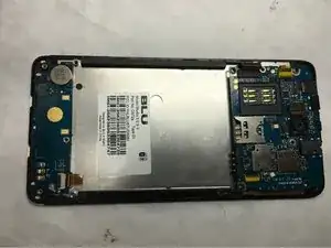
    • Remove the whole motherboard.

    • The Motherboard contains the headphone jack and the power button.

  14. dT43rB1Pnx1K51DW
    dT43rB1Pnx1K51DW
    AY4mITJjRCHqck5Q
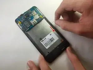
    • Peel off the bottom back with finger or supdger.

    • CAUTION: Adhesive is attached to the bottom circuitboard. May require extra effort to remove.

Abschluss

To reassemble your device, follow these instructions in reverse order with the screen replacement.
Curt Collingwood

Mitglied seit: 01/03/17

261 Reputation

0 Kommentare