Einleitung

This is a prerequisite-only guide! This guide is part of another procedure and is not meant to be used alone.

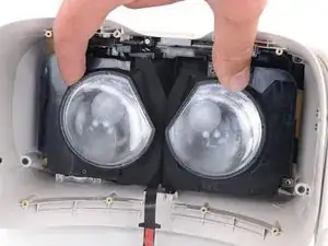
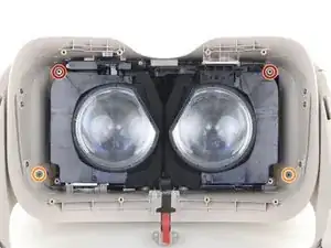
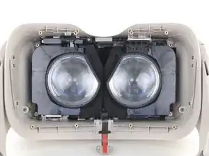
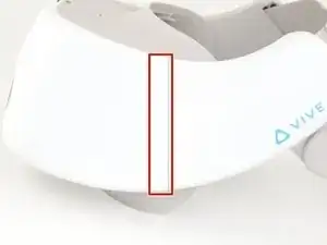
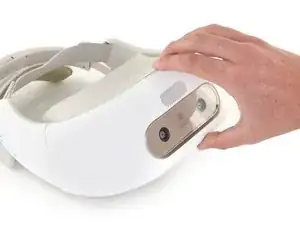
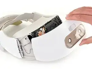
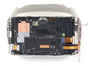
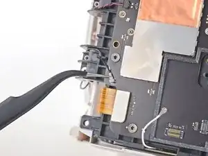
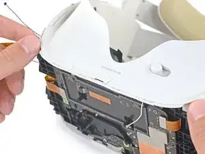
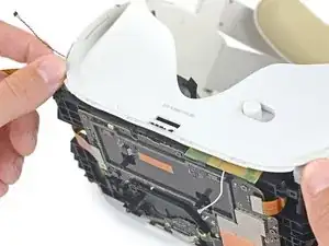
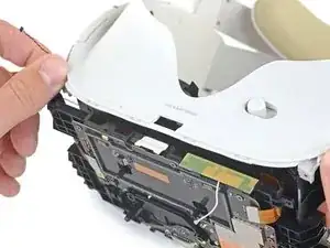
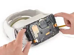
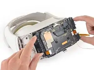
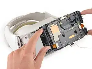
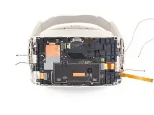
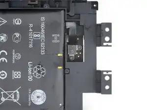
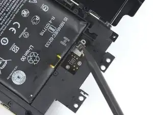
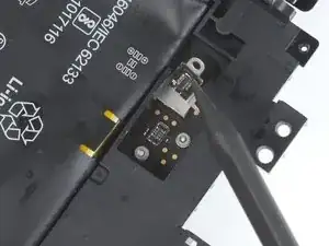
Follow this guide to disconnect the battery on a HTC Vive Focus.

Power down your device before you begin. Be careful not to power on your device while making repairs. If you accidentally power on your device, stop working and power it back off before you resume.

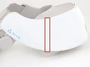
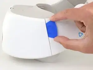
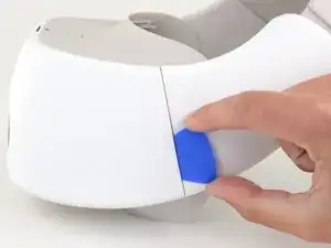
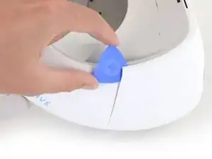
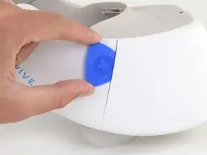
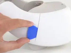
This repair requires breaking the plastic welds that help secure the front cover to the device. If you complete this repair, the gaps between the plastic front cover and side panels will no longer be flush. This damage is permanent but only cosmetic and will not affect the device’s functionality, usability, or operation.

  1. Fp1NhVVVWNPwZ5Rm
    Fp1NhVVVWNPwZ5Rm
    QBQscC6NcItQ3MOv
    LujRsVDea63DUAsJ
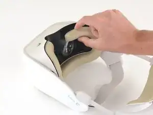
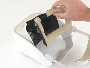
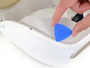
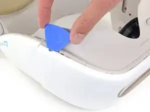
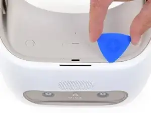
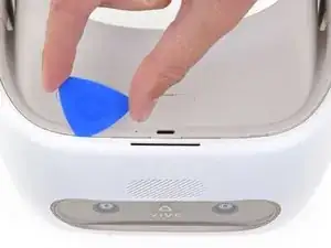
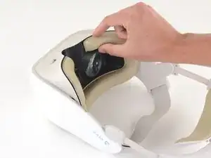
    • Place your device upside-down on your work surface.

    • The facerest cushion is lightly held into place by seven plastic clips.

    • Use your fingers to gently pull the facerest cushion straight off of the facerest to remove it.

  2. dOcqkGT13iM2dVRJ
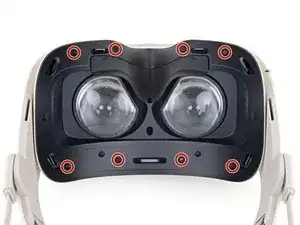
    • Use a T5 Torx screwdriver to remove the eight 4.5 mm screws securing the facerest.

    • One of the screws will be covered by a tamper-evident sticker. Press the driver through the sticker to remove the screw.

  3. dVLEUkMCAUP2dBHa
    dVLEUkMCAUP2dBHa
    sisrtLX4KAlPPImh
    JhgHcc3bnQvc3FVa
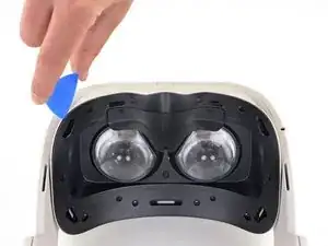
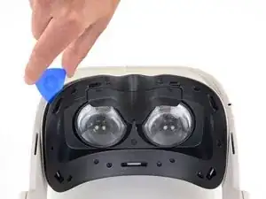
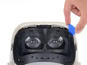
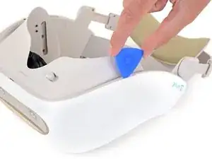
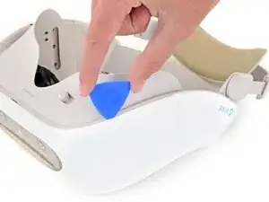
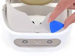
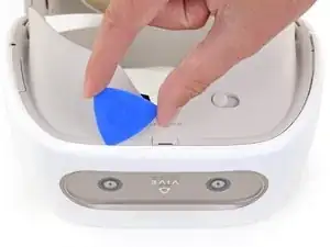
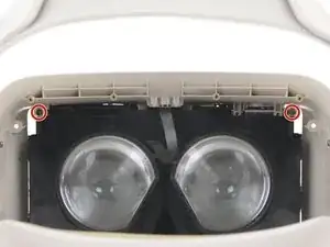
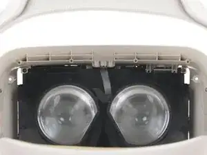
    • Insert an opening pick into the upper-left corner of the facerest.

    • Twist the opening pick to release the plastic clip securing the facerest.

    • Repeat for the upper-right corner.

    • Don't remove the facerest yet. It's still attached by the facerest sensor ribbon cable.

  4. kfWGDZXRaRjcfAGI
    kfWGDZXRaRjcfAGI
    vBxlbCZmn2vFQoWu
    6pHL4JgGnhuMACit
    • Carefully flip your device over.

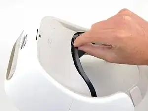
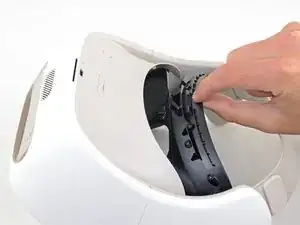
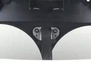
    • Pull the facerest out just enough to access the screws securing the facerest sensor.

    • Don't put any strain on the facerest sensor ribbon cable.

    • During reassembly, make sure the facerest sensor ribbon cable is positioned between the lenses before reinstalling the facerest.

  5. HaceRvZ1N4EXF22Z
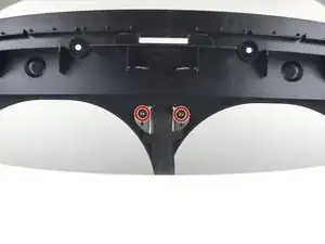
    • Use a T5 Torx screwdriver to remove the two 2.4 mm screws securing the facerest sensor to the facerest.

  6. WS3JwubqqwPvhZpy
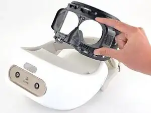
    • Remove the facerest.

  7. uaQExBifEq4XEFnG
    uaQExBifEq4XEFnG
    yBWPlTs3bL5uyLXH
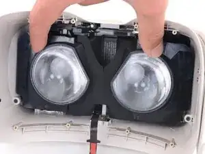
    • Use your fingers to slide the lenses towards each other so that they are positioned towards the center of the device.

  8. avxwI1aKRNtAhM6X
    avxwI1aKRNtAhM6X
    DQ6o3LoJtbfZDsGY
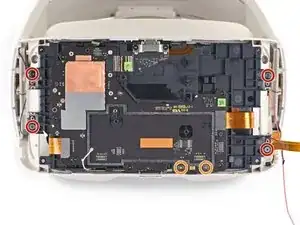
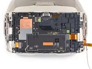
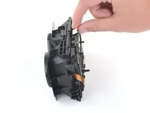
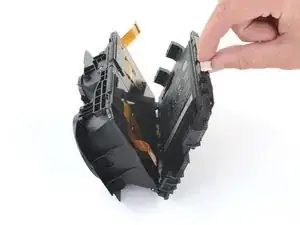
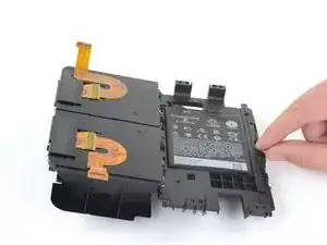
    • Use a T5 Torx screwdriver to remove the four screws securing the front cover from inside the device:

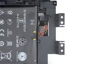
    • Two 5.7 mm screws with fine threads

    • Two 5.5 mm screws with coarse threads

    • The coarse-thread screws can strip easily. During reassembly, tighten the coarse-thread screws until they're hand tight and then no more.

  9. AGsmoR6QOpGU3wHK
    AGsmoR6QOpGU3wHK
    WarWYkXbOVXwMeW1
    • Note the location of the plastic welds on both vertical edges of the front cover.

    • After reassembly, the gap between the front cover and the side panels may no longer be flush. This is a cosmetic defect only and will not affect operation. The front cover's clips and screws are sufficient to secure it to the rest of the device.

  10. ldwptB1DTiCqAYoc
    ldwptB1DTiCqAYoc
    LlNbxhfu2YKIspgW
    pNxYRTYIIwBRpC3Q
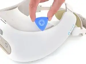
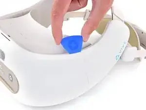
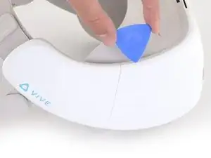
    • Insert an opening pick into the top of the front cover near the upper left corner.

    • Slide the opening pick around the upper left corner of the front cover.

  11. udEvlvFm3TaPF5HD
    udEvlvFm3TaPF5HD
    SJss4yxufVABvsMb
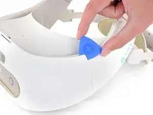
    • Use the opening pick to separate the weld securing the left side vertical edge of the front cover.

    • The weld may require significant force to separate.

  12. lpIWLwqclF3fICRI
    lpIWLwqclF3fICRI
    cGgJnU4Sa6Qy3F2D
    aTR4ENoAdgOSkZB3
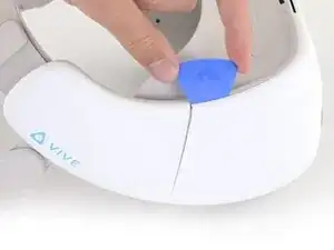
    • Insert an opening pick into the top of the front cover near the upper right corner.

    • Slide the opening pick around the upper right corner of the front cover.

  13. a1ZSpPxkOrWKWdxF
    a1ZSpPxkOrWKWdxF
    TvZPK2NSIfoVptW1
    • Use the opening pick to separate the weld securing the right side vertical edge of the front cover.

    • The weld may require significant force to separate.

  14. uU4MKVcIPajlQKIY
    uU4MKVcIPajlQKIY
    RqbhSprgSNMISgCo
    b2bbb5Uf2bvxAryg
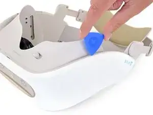
    • Flip the device upside-down.

    • Use an opening pick to disconnect the plastic clips securing the bottom right edge of the front cover to the device.

  15. FQD1aUflgyHWJW6c
    FQD1aUflgyHWJW6c
    Lf46BsA1WKCyeqHx
    • Slide the opening pick along the bottom edge of the front cover to separate it from the device.

  16. hJ2NZ4QtIMbKurgU
    hJ2NZ4QtIMbKurgU
    MDgI3YAiwbV4a6JT
    • Use the opening pick to disconnect the plastic clips securing the bottom-left edge of the front cover to the device.

  17. OofmPpQvit3ms3aJ
    OofmPpQvit3ms3aJ
    WKUq6EQUhk2Uq1ZJ
    • Flip the device right-side up.

    • Use the opening pick to separate the last few plastic clips securing the top of the front cover.

  18. lOFsi4Rp1YVSFJ15
    lOFsi4Rp1YVSFJ15
    Ow6GCmSuL23OnUHW
    • Remove the front cover.

  19. UmMMrNaYZdPFumuQ
    UmMMrNaYZdPFumuQ
    WuHlVYcFmWTruVqg
    NiuVJsXJntmWCwNl
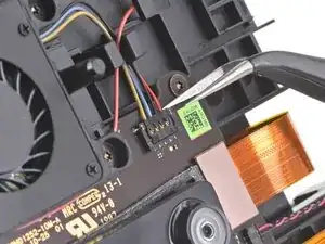
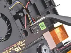
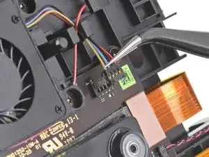
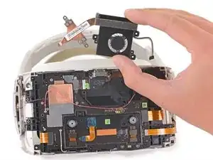
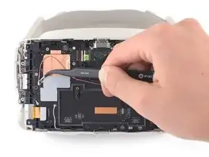
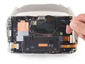
    • Use a pair of angled tweezers to disconnect the CPU fan cable from the motherboard.

    • Lift the CPU fan connector straight up from the motherboard to disconnect it from its socket.

    • During reassembly, align the CPU fan connector with its socket and use your finger to press it straight down into the motherboard.

  20. D2dymHdF11MIQbbn
    D2dymHdF11MIQbbn
    nkZqJoa4EwKsM2XA
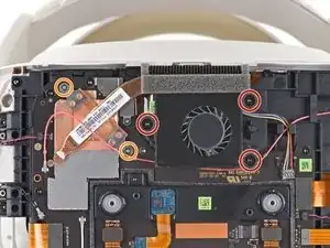
    • Use a T5 Torx screwdriver to remove the three 5.5 mm screws securing the CPU fan.

    • Use a Phillips screwdriver to remove the two 2.3 mm screws securing the CPU heatsink.

  21. YDvLVlBr22HtXfBQ
    YDvLVlBr22HtXfBQ
    BrZMTgDiYHI6jfWI
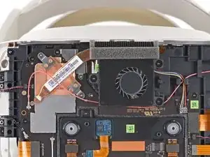
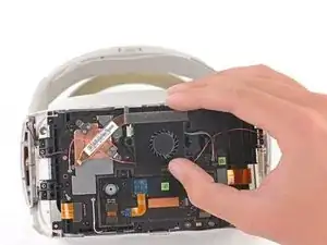
    • Remove the CPU fan.

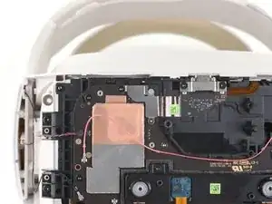
    • During reassembly, do not sandwich the red antenna cable between the heatsink and contact plates.

  22. lTGTuqvk4okMh1kf
    lTGTuqvk4okMh1kf
    WN6AbFPEPFsYslyM
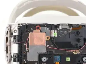
    • Use a T5 Torx screwdriver to remove the black 5.5 mm screw from the power button cable bracket.

    • Use a Phillips screwdriver to remove the 2.3 mm screw from the power button cable bracket.

  23. Op1af6DWR2PxCsD4
    Op1af6DWR2PxCsD4
    Bk5TZIMlHUZUsIsB
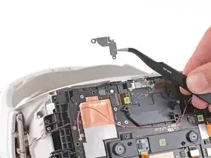
    • Use a pair of tweezers or your fingers to remove the power button cable bracket from the motherboard.

    • During reassembly, slot the power button cable bracket back onto the peg on the motherboard before reinstalling the screws.

  24. qThnQGANTO53ANhG
    qThnQGANTO53ANhG
    WQ4Nv2vDIOSaNfnA
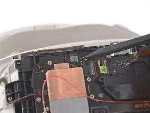
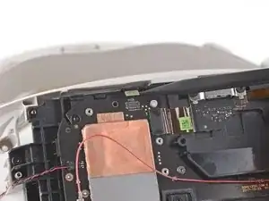
    • Use the pointed end of a spudger to disconnect the power button cable from the motherboard.

  25. ANYHegyXhZZJLmDt
    ANYHegyXhZZJLmDt
    y3cNqTepCuMaMTOr
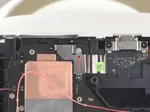
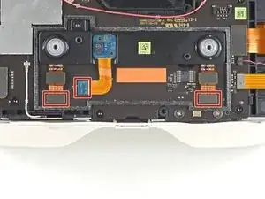
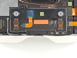
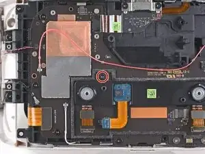
    • Pry up with the flat end of a spudger to disconnect the three ribbon cables connecting the proximity sensor array to the motherboard.

  26. vAQc4ABYudeBaDGX
    vAQc4ABYudeBaDGX
    rHPOPdLl5kD4HBfx
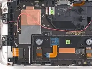
    • Use a T5 Torx screwdriver to remove the 4.5 mm screw from the proximity sensor array.

  27. EWSGl3xOQBDD2taU
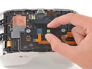
    • Remove the proximity sensor array from the motherboard.

  28. PHWNhQnOqxPLsA5e
    PHWNhQnOqxPLsA5e
    toCUVLoHArcixaph
    G2tZVOqwlI6JrGdl
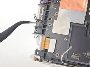
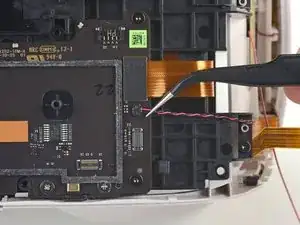
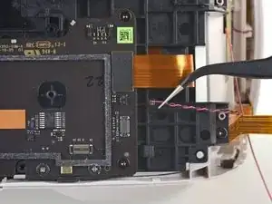
    • Antenna connectors are fragile and can break off of the motherboard. Use this technique when disconnecting antenna cables.

    • Use a spudger or a pair of tweezers to disconnect the red antenna cable from the front of the device.

    • De-route the antenna cable from the front of the device and place it to the side.

    • During reassembly, be sure to re-route the cable through the brackets and clips securing it.

  29. plVbV5GN5PjPrTqG
    plVbV5GN5PjPrTqG
    RCS36HZ2GndX1YAI
    O2FEIldNTTyMuCbm
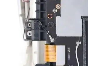
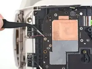
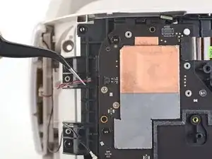
    • Use a spudger or a pair of tweezers to remove the black antenna cable from the motherboard.

    • During reassembly, re-route the black antenna cable through its channel and clip.

  30. wDkZMlDrHVOJh1rX
    wDkZMlDrHVOJh1rX
    nVWGxHJMfxW1ijjt
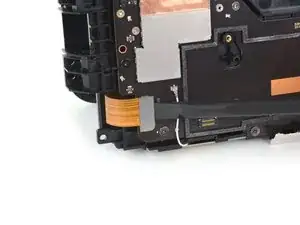
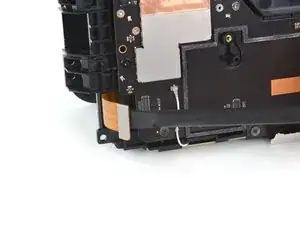
    • Use a spudger to disconnect the ribbon cable connecting the volume buttons and headset jack to the motherboard.

  31. iEnsYQ3hBSRAv4PV
    iEnsYQ3hBSRAv4PV
    WaDPGYajFSavNv5B
    • Use a pair of tweezers to carefully disconnect the speaker wire from the right side of the motherboard.

    • During reassembly, reinstall the speaker wire with the gold contacts facing towards you and the red wire on top.

  32. KSOxFsAcxyxOPwWS
    KSOxFsAcxyxOPwWS
    36atHMZTjOyEZACe
    • Use a pair of tweezers to carefully disconnect the speaker wire from the left side of the motherboard.

    • During reassembly, reinstall the speaker wire with the gold contacts facing towards you and the black wire on top.

  33. VM6b4cV5OAg4i24r
    VM6b4cV5OAg4i24r
    guhhPud4kJR1Zwuj
    • Use a T5 Torx screwdriver to remove the four 5.6 mm screws securing the corners of the internal assembly to the frame.

    • Use a Phillips screwdriver to remove the two 7.2 mm silver screws from the bottom of the motherboard.

  34. yGuXMAurlaNRwXkG
    yGuXMAurlaNRwXkG
    Uy6Xm52nOceRAoan
    • Use a T5 Torx screwdriver to remove the two 5.5 mm screws securing the internal assembly to inside of the frame.

    • During reassembly, make sure the internal assembly is fully seated on its centering pegs on each side and sits flush on the tabs on the frame before tightening these two screws.

    • Check for proper rack and pinion operation before continuing reassembly.

  35. HDMnYUTyqk154Iri
    HDMnYUTyqk154Iri
    AIFJCYmdnXRl2yJ5
    • Use a T5 Torx screwdriver to remove the two 4.5 mm screws securing the bracket under the left lens.

  36. uk5Gjk34gBWLvBZH
    uk5Gjk34gBWLvBZH
    JlAnEljGqpGTl3Sq
    • Remove the bracket under the left lens.

    • To ensure correct operation, make sure this piece is properly seated on the adjuster mechanism by sliding the lenses as close together as possible before reinstalling it.

  37. QmZxdjQAEKph2pVn
    QmZxdjQAEKph2pVn
    Qrf2hqt5D3yyKFXi
    WhKNHxOW35DMsJ3L
    • Before removing the internal assembly, tilt the front out slightly to feed the microSD card slot cover through the frame.

  38. tQJVIJdoOupkoKOF
    tQJVIJdoOupkoKOF
    ltLApt4TDAvIT3Da
    KhSUYJSXFVSGJ4U1
    • Carefully remove the internal assembly through the front of the device.

    • The internal assembly may not come out easily. Gently bend the outer frame as necessary to create space for the edges to clear.

    • Do not force any part of the internal assembly out.

    • During reassembly, feed the microSD slot cover referenced in the previous step back through the frame as you slide the internal assembly back into place.

  39. wILTtuIE34vAca1K
    wILTtuIE34vAca1K
    lUar6UHRBYA5qxfG
    • During reassembly:

    • Make sure not to trap any of the five loose wires and cables when reinstalling the internal assembly.

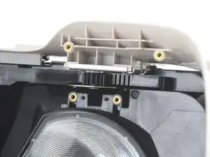
    • Hold the lenses as close together as possible and align the rack and pinion with the gear and washer.

    • This will ensure the lenses are properly aligned.

  40. bSHyqRCNiEhxURAU
    bSHyqRCNiEhxURAU
    fnxUPheCjPUsM2KG
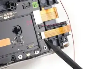
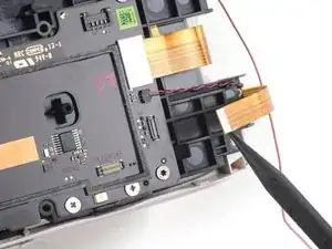
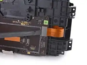
    • Use the flat end of a spudger to disconnect the left LED display ribbon cable from the motherboard.

  41. UbFseN6xuUT2EIvl
    UbFseN6xuUT2EIvl
    wiRhNFefOgkcudMu
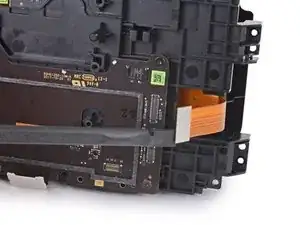
    • Use the flat end of a spudger to disconnect the right LED display ribbon cable from the motherboard.

  42. NCOQnaATdgKUmCB5
    NCOQnaATdgKUmCB5
    lAsDxaciXCLFkGvQ
    W4MOn4AEBSHdeWQo
    • Swing the midframe open to access the battery.

    • During reassembly, be careful not to crush the LED display ribbon cables when folding the midframe back into place.

  43. aiWuoERKeGKmIAEa
    aiWuoERKeGKmIAEa
    BAPWXuFEkOYtOhiW
    • Use a Phillips screwdriver to remove the two 2.3 mm screws securing the battery cable to the back of the motherboard.

  44. KdRCrTYXP1AWybdX
    KdRCrTYXP1AWybdX
    3xESFh2HfuWvjjsu
    • Use the tip of a spudger to disconnect the battery from the back of the motherboard.

    • During reassembly, use a spudger to align the battery connector screw holes and press it into place.

Abschluss

To reassemble your device, follow the above steps in reverse order.

Repair didn’t go as planned? Try some basic troubleshooting, or ask our Answers community for help.
Sam Omiotek

Mitglied seit: 25/02/19

59342 Reputation

0 Kommentare