Einleitung

This guide will show you how to:

  • Remove the battery
  • Remove the front panel
  • Replace the LCD screen
  1. RoZUgjn1vegYPdsF
    RoZUgjn1vegYPdsF
    NWfSjdmwNlkKIqFR
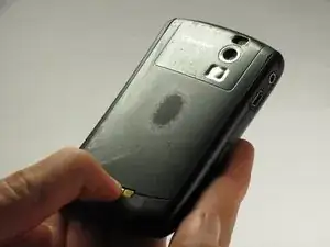
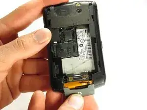
    • Hold the phone with the back facing you.

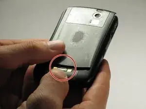
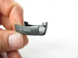
    • Press the silver tab down and remove the cover.

  2. pjFWOKAtpS1SbumG
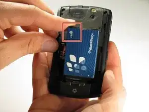
    • Pull up on the top edge of the battery to remove it.

  3. KGKCxSiDMILiBMoo
    KGKCxSiDMILiBMoo
    v2QMDnhs4yXABrkS
    EfHEX2gTmjn4od1L
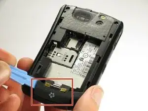
    • Use a plastic opening tool to gently pry the bottom cover loose.

    • Do not use excessive force at risk of damaging the antenna, which is under this casing.

    • Pull the cover from the front of the phone after the back is loose.

  4. a1k3Sf6FEyCAWPJI
    a1k3Sf6FEyCAWPJI
    KCr2GbXLfpGJAUvg
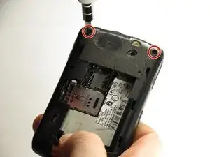
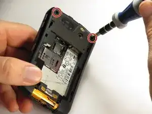
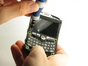
    • Remove the two top screws with a T5 Torx screwdriver.

    • The screws are 8mm long.

  5. vxy4t5IvLlmlOGGV
    vxy4t5IvLlmlOGGV
    LDluN4a3exW4GxCL
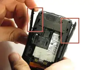
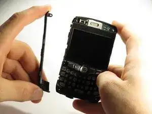
    • Gently pry off the side casings from the top.

    • The side casings cannot be fully removed yet because they are screwed on at the bottom.

    • You will not need to remove the sides on the bottom.

  6. KCUrZevPDgQDfyed
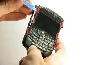
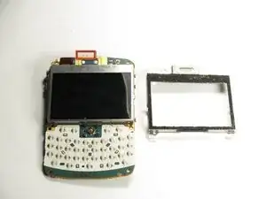
    • Use a plastic opening tool to detach the securing clips holding the the front panel in place.

    • There are six securing clips total.

  7. ZvWBqIBCKswUPDQx
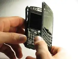
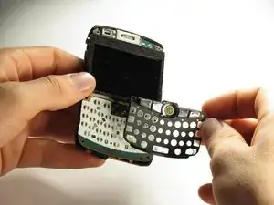
    • Carefully remove the front panel.

    • You may need to apply some force in removing because the front panel is attached to the rest of the device with adhesive.

  8. UmXJSm2UMGi12NAN
    UmXJSm2UMGi12NAN
    d2f5s2GuvIaLpSxK
    MhSUNjGCOJBMFOGk
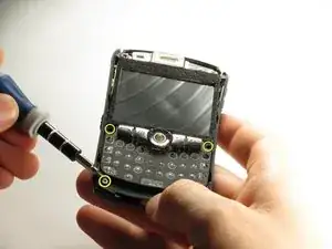
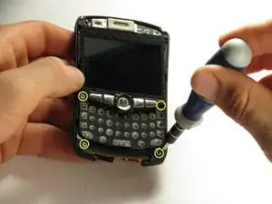
    • Use a T6 Torx screwdriver to remove the four screws located on the corners of the keyboard frame.

    • The screws are 6mm long.

  9. QtDvJtkj1cIXY21V
    QtDvJtkj1cIXY21V
    EbvoJgMlwIwZmOpt
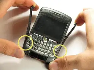
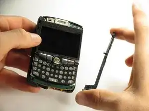
    • After the bottom two screws have been removed the side casings can be removed.

  10. RhBGn3ReKWDTCr6W
    RhBGn3ReKWDTCr6W
    Ph2idjV1w3OIdeNY
    EPloQNEKV5pxltFe
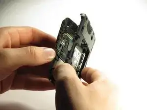
    • When all four screws are removed, the keyboard frame, screen housing, screen, and back casing can be separated.

    • The screen frame hooks on to the top of the motherboard with a small tab on the motherboard.

  11. kF3JpHc4vvRYJN2u
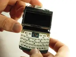
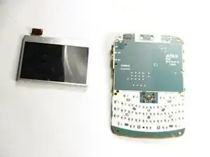
    • Place the motherboard on a flat surface with the LCD screen face up.

  12. oQJ1YYBVY3uvSKE1
    oQJ1YYBVY3uvSKE1
    j6LQxAblPSErAR36
    HfwrGohGrb66Ipwr
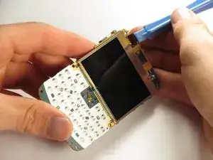
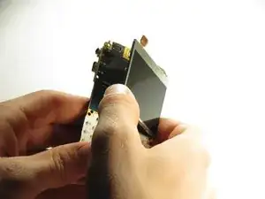
    • Using a plastic opening tool, gently pull the connector directly up from the motherboard.

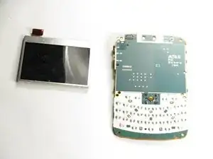
    • Remove the LCD screen from the motherboard.

    • The screen is attached to the motherboard with adhesive.

Abschluss

To reassemble your device, follow these instructions in reverse order.
Christopher Aiello

Mitglied seit: 12/10/11

89 Reputation

0 Kommentare