Einleitung
Werkzeuge
-
-
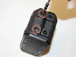
To remove the outer casing, use a 3mm Hex bit to remove the 4 large 12mm Hex screws on both sides of the device.
-
-
-
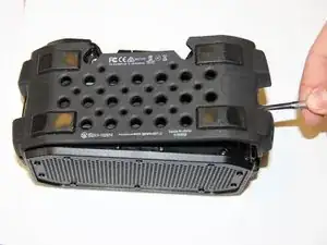
Using the Metal Spudger, carefully pry each side of the rubber casing away from the device.
-
-
-
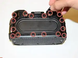
To remove the inner plastic casing, use a Phillips #00 head bit to remove the 16 small 9mm screws surrounding the top side of the device.
-
-
-
Carefully lift away the housing and replace the broken casing/component. Replace using the new casing.
-
-
-
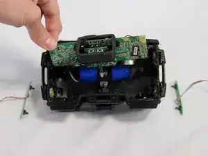
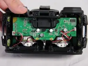
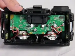
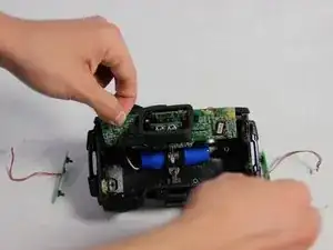
To remove the motherboard, proceed to unscrew the 3 Phillips #00 bit type, 13mm long screws located on both sides of the motherboard.
-
-
-
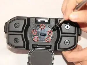
Then, proceed to unscrew the 5 Phillips #00 bit type, 9mm long screws located on the face of the charging dock.
-
-
-
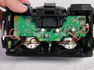
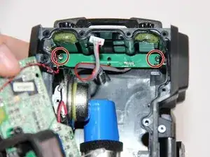
Disconnect the two 4-pin auxiliary button register cables connected on both sides of the motherboard.
-
-
-
To remove the button registers, unscrew the two Phillips #00 bit type, 6 mm screws found on both sides of the control registers.
-

To reassemble your device, follow these instructions in reverse order.
Ein Kommentar
Great guide! Do you know the spec/name of the button registers so that I can purchase a new one to replace a dysfunctional one?