Einleitung
Werkzeuge
Ersatzteile
-
-
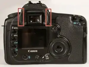
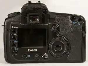
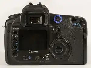
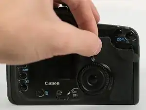
Peel off the rubber grip on the back by grasping one of the corners and pulling it away from the camera body.
-
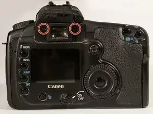
Once removed, a hidden screw is revealed.
-
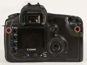
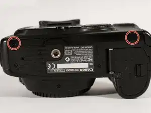
Remove both screws from the rear of the camera.
-
-
-
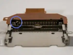
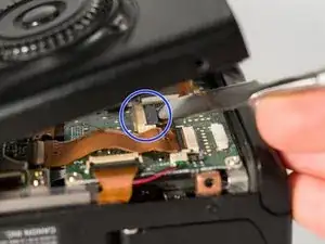
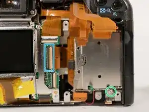
Flip the lock on the flex cable connector up with a spudger.
-
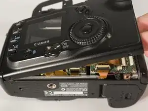
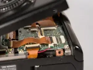
The front panel should pop off, now that the cable has been disconnected.
-
-
-
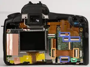
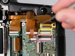
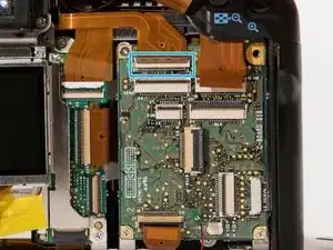
Disconnect all the indicated connectors by opening their latches.
-
Remove the flex cable that connects the logic board to the secondary control board.
-
Pull the small green connector out of its socket. Be careful when removing it, as it is possible to tear the tiny wires running into the connector.
-
Disconnect the two hidden connectors under the top connector indicated in pink.
-
Disconnect the third hidden connector.
-
-
-
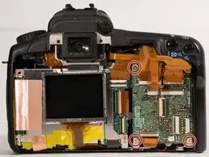
Remove the three screws from the edges of the board.
-
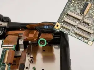
Flip the board up and out so that the ground connection can be unscrewed.
-
-
-
Open the connector for the CF slot.
-
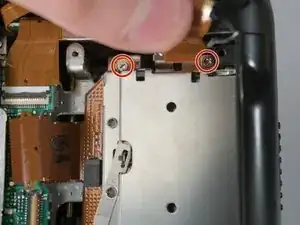
Remove the screw that attaches the bottom of the CF slot.
-
Remove the two last screws attaching the top of the CF slot.
-
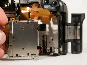
Remove the CF slot.
-
-
-
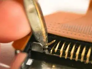
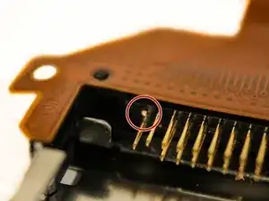
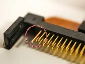
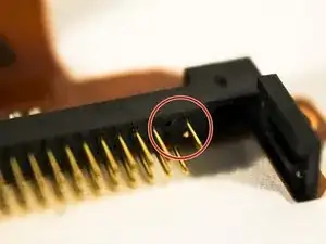
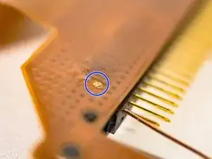
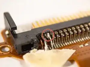
I was able to relatively easily replace the pin that snapped with a section of solid-core wire from an ethernet cable.
-
-
-
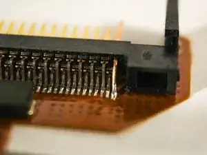
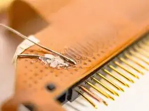
Some pins had gotten pushed in far enough that they ripped up traces, so it was necessary to reroute their connections from the bottom vias.
-
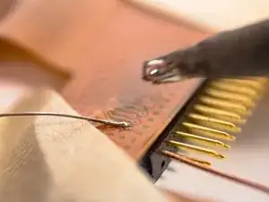
To be able to solder to the vias, you have to scratch the solder mask off of them with a sharp tool like an Xacto knife.
-
Then it can finally be soldered to with a high gauge wire. I took a section of larger stranded-core wire, cut it, and unwound it.
-
-
-
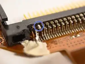
This is one of the cases in which I was able to reuse a pin that was broken internally but not externally, simply by pushing it back into place and running a wire from the piece left inside.
-
Make sure not to leave large lumps of protruding solder like the one here. I ended up having to slim it down, since it touched the metal housing of the connector when I put it back together.
-
Hopefully when you reassemble your EOS 20D, you won't be getting the "Err CF" message anymore.
-
To reassemble your device, follow the disassembly instructions in reverse order.
6 Kommentare
Thank you! Great guide))
Thanks! I’m glad you found it helpful!
Let me know if you have any questions about repairing the 20D :)
Alec M -
i have a problem, when my pin memory broken, just one pin, and the line almost completely removed, pleas help me
Hi!
What exactly is your problem? It sounds like you’re saying that the pin is broken. What does “the line is almost completely removed” exactly mean though? If it’s a broken trace on the top side, don’t worry, you can run wires from the vias on the opposite side to fix that.
Alec M -
