Einleitung
Werkzeuge
-
-
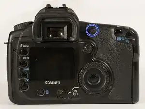
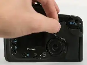
Peel off the rubber grip on the back by grasping one of the corners and pulling it away from the camera body.
-
Once removed, a hidden screw is revealed.
-
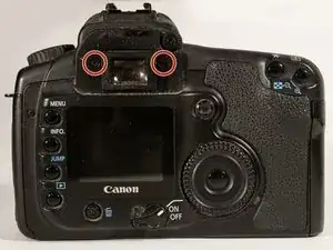
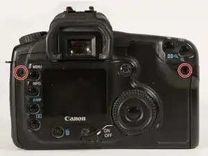
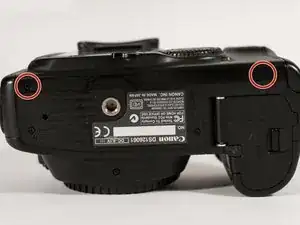
Remove both screws from the rear of the camera.
-
-
-
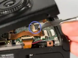
Flip the lock on the flex cable connector up with a spudger.
-
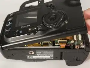
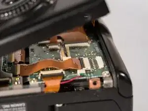
The front panel should pop off, now that the cable has been disconnected.
-
-
-
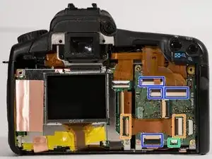
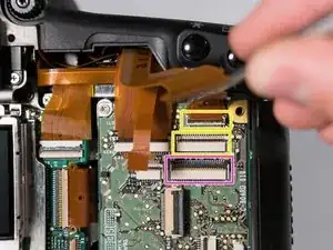
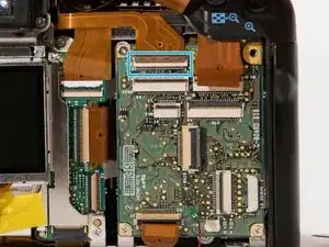
Disconnect all the indicated connectors by opening their latches.
-
Remove the flex cable that connects the logic board to the secondary control board.
-
Pull the small green connector out of its socket. Be careful when removing it, as it is possible to tear the tiny wires running into the connector.
-
Disconnect the two hidden connectors under the top connector indicated in pink.
-
Disconnect the third hidden connector.
-
-
-
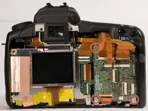
Remove the three screws from the edges of the board.
-
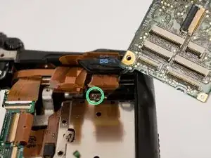
Flip the board up and out so that the ground connection can be unscrewed.
-
To reassemble your device, follow these instructions in reverse order.
