Einleitung

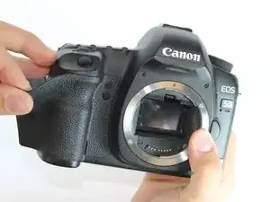
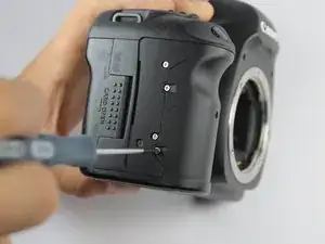
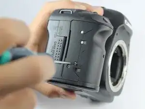
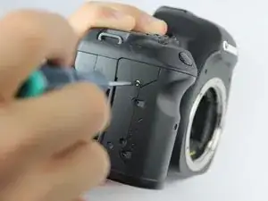
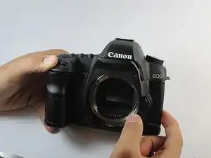
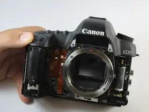
This guide will show users how to remove the front panel. It is necessary to remove the front panel in order to remove the top panel and access many internal components.

  1. A5um5QnBoChAkGjG
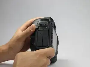
    • Peel back the rubber cover above the in/out ports to reveal two screw heads.

  2. yJraDyNfYahSnHCm
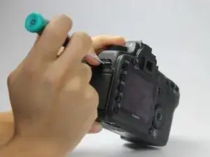
    • Remove both 5.4 mm screws using a Phillips #0.

    I just accidentally stripped one of those screws. Is there anything I can do or am I...screwed?

    Casey Ayers -

  3. 43i6cjhXN5AKZ1OH
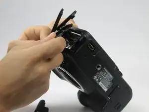
    • Lift the in/out port plastic covering from the bottom where the backup battery used to be.

    Before removing the port cover, you must also remove the screw to the left of the mic jack and the screw below the HDMI port.

    Teovall -

  4. 2BWxE3lMBaUExfVV
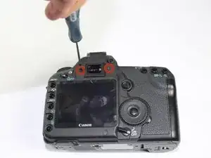
    • Remove each 6.3 mm screw on either side of the viewfinder using a Phillips #0 screwdriver.

    It is important to remove the diopter adjustment screw and the diopter wheel above the right screw. Otherwise you will not be able to take off the top panel in step 22.

    Per Feet -

    Use Phillips #00 screwdriver.

    Mr Blueeye -

  5. hALDcihdXSo1DF2a
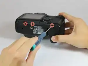
    • Remove the three 4.8 mm screws on the bottom of the back plate using a Phillips #0.

    The screw on the left side of this photo is shorter than the other two.

    rakurai -

  6. jQa4pIfbeHXPUKZt
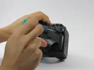
    • Peel back the rubber covering next to the menu dial to access the screw.

    • Remove the single 3.4 mm screw using a Phillips #0.

  7. lRaAjCR2kAxLpQ3R
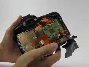
    • The back panel can now fall off easily by turning the device upside down. Be sure to catch it so the data ribbons do not tear or tug.

  8. UWkkLRibvmBEmkqb
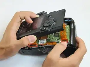
    • Remove each data ribbon cable from the motherboard by applying pressure down towards the motherboard and gently sliding your thumb upwards on the slot where the cable meets the motherboard. This will raise a very small clip that locks the cable in place.

    • The back panel is now free from the rest of the device.

  9. eXkph4sYVIH6cWkv
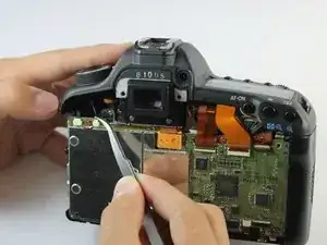
    • Using tweezers, pull out the wire attaching the front panel to the motherboard.

  10. EGkvlUhEeZWKiigG
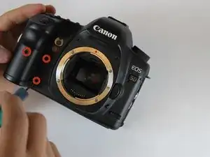
    • Peel off the rubber cover on the front panel in order to access the screws underneath.

  11. 6ZTamgVHvhVEOYPw
    • Remove each of the 4.9 mm three screws using a Phillips #0.

  12. 2N6HhICN3QudVNSK
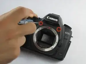
    • Remove the two 4.8 mm screws above where the lens would be using a Phillips #0.

  13. mKwJWSFmoUHjnHuH
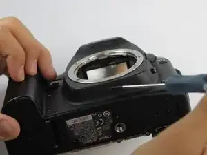
    • Remove the single screw underneath where the lens would be using a Phillips #0.

  14. JxK32FY4BrkUxV22
    JxK32FY4BrkUxV22
    EPWgwbDyTn4MtE45
    YpdjkliahumMGSjG
    • Remove the four 3.0 mm screws next to the memory card reader using a Phillips #0.

  15. PeB2RBLv6SKx1KSF
    PeB2RBLv6SKx1KSF
    MtLdhv5KneiuOThv
    • Remove the front panel by lifting upwards from the right side where the in/out ports used to be.

    You need to remove the in/out port side panel first. There are two screws next to the mic in and below the HDMI out ports to remove.

    Radian -

Abschluss

To reassemble your device, follow these instructions in reverse order.

Mike Seed

Mitglied seit: 22/09/14

2956 Reputation

Ein Kommentar

Good write-up. I just replaced my casing using these instructions.
sebastien -