Einleitung
In order to replace internal components of the camera, the rear cover needs to be removed. This is a time consuming process, so make sure you have enough time to finish it. Do not rush as there are many different screw sizes. Keep screws and removed parts organized properly.
-
-
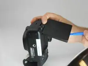
Take the LCD out of its place to expose the Phillips #PH00 screws.
-
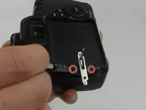
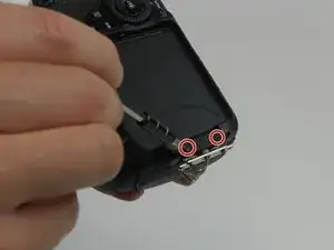
Remove the two 2.5 mm Phillips #PH00 black screws on both sides of the LCD screen.
-
Next remove the two 3 mm Phillips #PH00 black screws near both sides of the base where the screen swivels.
-
-
-
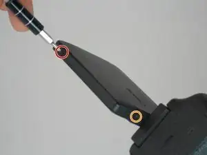
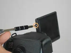
Remove the 3 mm Phillips #PH00 silver screw on the side of the screen.
-
Turn the screen to remove the second 3 mm Phillips #PH00 silver screw.
-
-
-
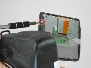
Using the tweezers, carefully disconnect the rear connector by pulling it away from the screen.
-
-
-
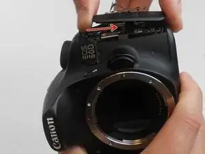
Now, four 2.2 mm Phillips #PH00 screws holding a cover around the hinge should be visible.
-
Turn the swivel around to expose the remaining of the aforementioned screws.
-
Then use the PH00 screw driver to remove them.
-
-
-
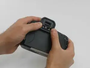
The eye piece will slide right off with a firm push upwards.
-
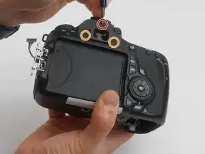
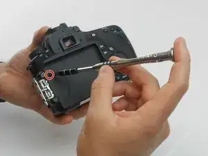
Remove the 3.4 mm Phillips #PH00 screw using a PH00 screw driver.
-
Remove the two 9.9 mm Phillips #PH00 screws using the PH00 screwdriver.
-
-
-
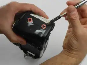
Using the PH00 screwdriver, remove the 3.8 mm Phillips #PH00 screw located on the back of the camera.
-
-
-
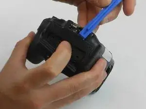
Using the plastic opening tool, carefully pull up the rubber grip around the port side of the camera.
-
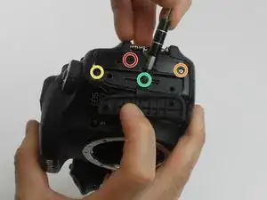
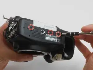
Remove the four different sized screws located beneath the rubber grip.
-
6 mm Phillips #PH00 screw.
-
3.4 mm Phillips #PH00 screw.
-
3.9 mm Phillips #PH00 screw.
-
2.2 mm Phillips #PH00 screw.
-
-
-
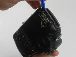
Remove two 4.8 mm Phillips #PH00 screws from the memory card side of camera using the PH00 screwdriver.
-
-
-
Look at the bottom of the camera so the serial number tag reads up right.
-
Using the PH00 screw driver, remove the top three 3.5 mm Phillips #PH00 screws.
-
-
-
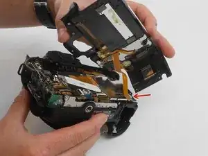
Now gently pull the back cover off the camera.
-
Gently pull the orange wire connected to the motherboard of the camera up and off of the motherboard.
-

To reassemble your device, follow these instructions in reverse order.
The screws (in orange) near the swivel base are shorter, 2.5mm. Also do not remove the screws (in red) on either side of the screen, it is unnecessary for removing the rear cover. See my comment on the next step.
rakurai -
The first 4 steps aren’t necessary
Dave Common -