Einleitung
For the disassembly of the plastics part of the device, see the very good tutorial
Https://www.youtube.com/watch? v=rxc9C1UrVVs
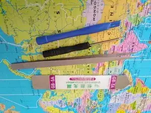
Werkzeuge
Ersatzteile
-
-
Also look at the pdf file or I have some photos that could not be deposited in this tutorial
-
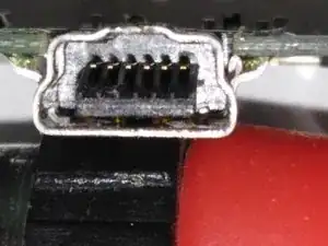
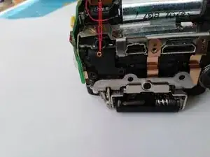
Photograph of the broken plug, the central part is no longer centred and moves, hence the loss of USB connection with the computer
-
-
-
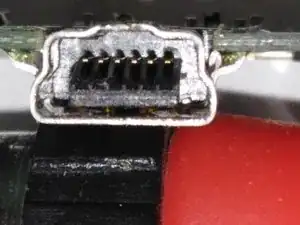
Seen from the broken socket, the central part almost no longer holds and goes wrong
-
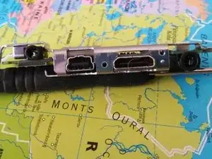
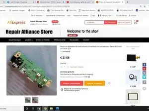
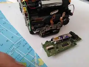
Photo of the item to be replaced (new card)
-
-
-
- For the disassembly of the complete plastics of the device, Proceed according to this very good video:
-
-
I attach here the links to his other videos that allow you to go further in disassembly (useless in our case). - Video #2, Removing The Circuit Boards https://youtu.be/_-gQbCM7QMw
-
- Vidéo #3, Suppression de l'assemblage CCD/Boîte de miroir/Shutter https://youtu.be/ZUZVH6Bfxfs - Vidéo #4, Putting It All Back Together https://youtu.be/7gJr4ANik-g - Vidéo #5, Power Switch & Mode Selector Switch Repair https://youtu.be/rpE7Co3df
-
-
-
- Video #7, Repairing The Set Button And Control Dial https://youtu.be/zaJJqRCfYXc - Video #8, Testing The Power Board https://youtu.be/yeCrpv_u1Zw
-
-
-
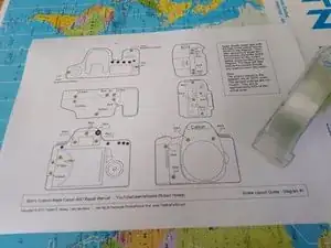
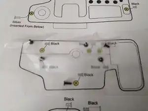
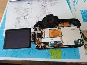
Download this page DIagram #1: http://www.thebobfactor.com/Canon%206... - Print the - You have the position of all the screws and at each screw disassembled, glue it with a small tape tape, which will allow you to know or put it back to rewind
-
There are two other boards, if you need to go further in disassembly (not necessary in our case). Diagram #2: http://www.thebobfactor.com/Canon%206... Diagram #3: http://www.thebobfactor.com/Canon%206...
-
-
-
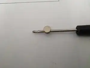
Small tip, to avoid losing the screws I put a magnet so that the screws are "glued" to the screwdriver
-
-
-
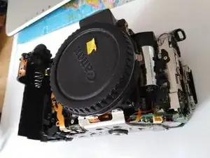
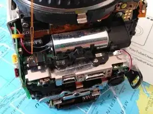
Once this video has been dismantled, you must see this
-
We can move on to disassembly the card
-
-
-
There are 5 screws left to loosen and 6 connecters to unbutton
-
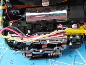
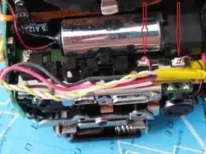
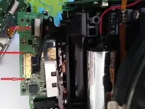
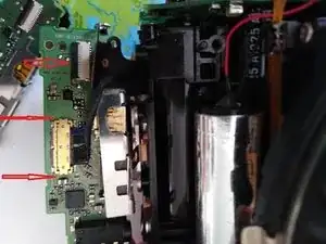
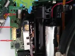
Start removing the 2 connecters in photo 1 with a tweezer, take on the side of the plug without pulling the wires
-
-
-
3 screws to remove, one of which is hidden under the yellow tape
-
Remove the plastic cable holder
-
-
-
Detach the tablecloth by pulling underneath with a flat screwdriver or with an unfolded paper clip in the hole provided for this purpose
-
-
-
This is the most delicate part to gently clear the card by moving it without forcing it, until it finds its pivot point
-
Be careful, because at the moment there is still a connecter connected under the card. However, the cable is long enough to take it out without worry
-
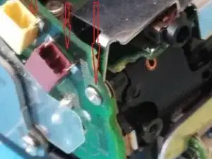
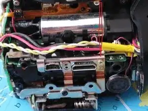
At the curvature of the red thread, a small bent visible next to the screw hole is observed. It is probably he who makes it so difficult to remove the card.
-
There is a second one on the upper part of the card next to the screw that was under the yellow tape.
-
-
-
The connecter undoes very easily by levering on each side of the golden connecter
-
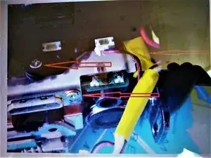
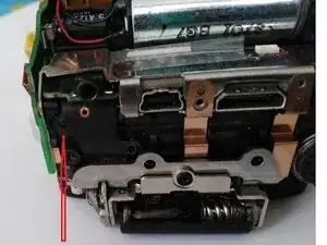
The wide arrow indicates where to pin the soft tablecloth
-
-
-
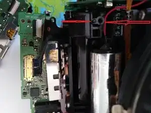
We see where the plastic pin is located that holds the printed circuit board, next to the screw hole
-
Locate the same principle on the top of the map
-
-
-
Reinsert the tablecloth into its connecter, without forcing, the hole of the tablecloth must be in the plastic pin to be in place
-
-
-
Be careful, the screw on the side comes to the arrowhead, the other hole must remain free for the screw of the plastic case (I was wrong)
-
-
-
Proceeding with the opposite of the video, everything went well.
-
Just when you put the rear facade back, the screen no longer folded down completely, don't panic, just unlock the three side screws of the card you just changed. The different plastic parts must join without leaving an apparent day.
-
Review the end of the video or this problem is well explained, it is thanks to it that I solved this little problem
-
To reassemble your device, follow the instructions in reverse order.
