Einleitung
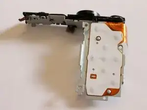
This guide will be used to replace buttons that are non responsive. The buttons are a critical component to any camera. They allow you to access features within the camera. They are required to take photos and even turn the camera on.
Werkzeuge
-
-
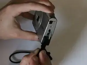
Open the latch at the bottom corner of the device to reveal the battery and SD card housing.
-
There is an orange latch holding the battery in place which must be pushed back in order to free the battery.
-
Once the battery is removed push the SD card and this will activate a spring ejecting the card from the camera.
-
-
-
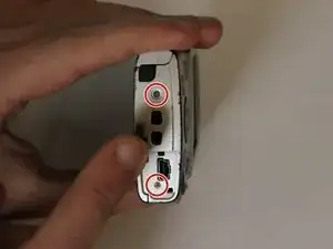
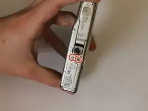
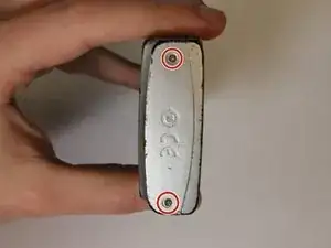
Remove the 6 Phillips #00 exterior screws from the camera. Two are located on the bottom and two are located on either side as shown. Notice that one of the screws is under the AV Out Digital flap on the side. All exterior screws should be 2.4mm in length
-
-
-
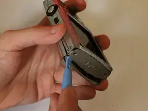
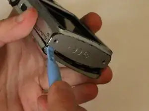
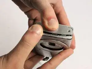
Pry apart the camera casing using the plastic opening tool tool provided. Once the casing has begun to separate pull the two sides apart with your hands.
-
-
-
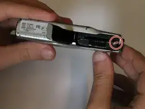
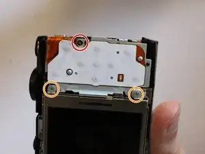
Remove the single philips #00 screw on the button pad which are 2.2mm long. This screw is circled in red in the guide image.
-
Next, remove the two 2.4mm long screws located in between the LCD screen and the touch pad. These screws will require a Phillips #00 screwdriver.
-
-
-
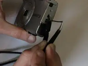
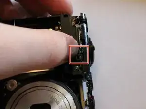
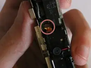
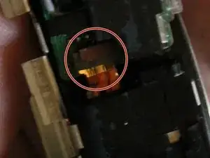
Remove the circuit ribbon connecting the flash to the camera in order to proceed to the next instruction.
-
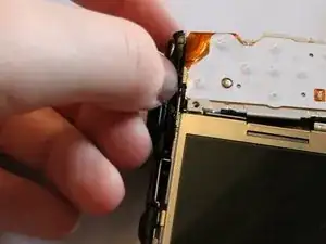
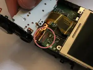
Carefully pull out the circuit ribbon from the camera which should be the last piece holding the button pad onto the camera.
-
To reassemble your device, follow these instructions in reverse order.
