Einleitung

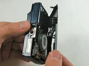
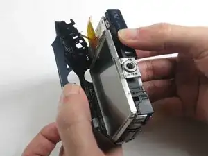
Replacing the LCD Display should be done when the display has been damaged or it has been determined that the LCD is no longer functioning. This will take some time. Handle the display with care once you reach the component as it is attached to several other vital components.

  1. MGHPURReCQMFWQQW
    • Place thumb on area right next to where it says open and slide to the right to open.

  2. APP4iGVpQvboSDJH
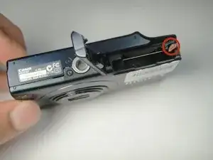
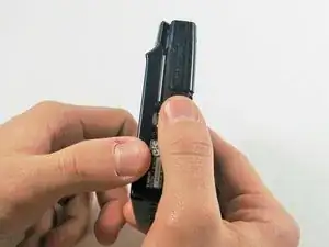
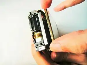
    • Remove the battery by pushing the orange object outwards; the battery will spring up and out.

  3. YHvZvvDp1Lw22E4T
    YHvZvvDp1Lw22E4T
    521ZTHPSfwIsVQFe
    • Remove the two 5.00 mm screws in the bottom of the casing with a Philips #000 screwdriver

  4. JHLINlf1JtbpokXD
    JHLINlf1JtbpokXD
    dNJMebRDgyjkHhLS
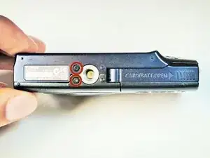
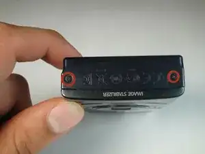
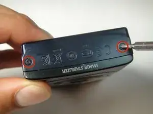
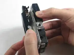
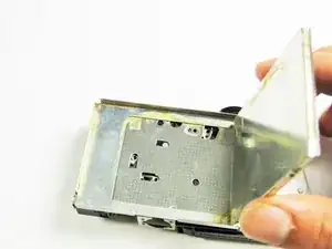
    • Place the camera on to the side that has the image stabilizer label.

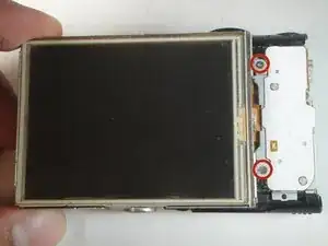
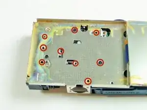
    • Remove the 5.00 mm screws that are on this side using the screwdriver.

  5. fGNKoCoFpplXvIZc
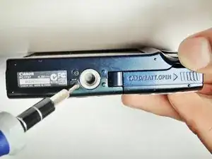
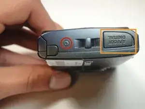
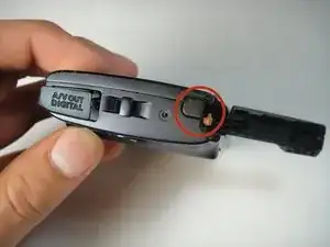
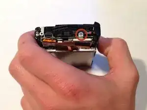
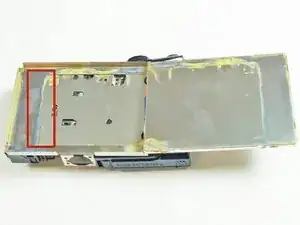
    • Place camera on to the side with the A/V Out Digital Cover facing up.

    • Remove this visible 5.00 mm screw.

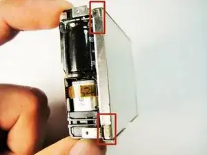
    • Pull the A/V Out Digital cover back to uncover the next step.

  6. DROQfALIP1QFaHQd
    • Remove the 5.00 mm screw from behind the cover.

  7. HwOC4FthE3dHjROY
    • Make sure the battery cover is open.

  8. jFQMUKYKYgpymwK1
    jFQMUKYKYgpymwK1
    Q5KdUAK5XplRtUhC
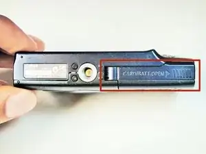
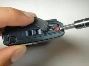
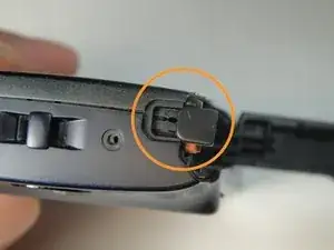
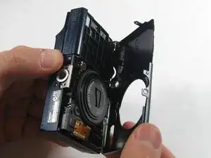
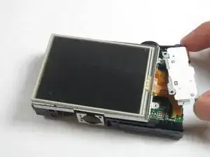
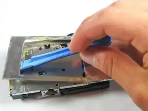
    • Turn the camera onto the side with the A/V out Digital cover.

    • Use your finger to pull this tab to the right.

  9. jKVQTSdbJJuZYA3r
    jKVQTSdbJJuZYA3r
    TwIOQnFJCHoEervc
    IEYTnOooRI5tnoGK
    • Remove the lens side by using your fingers or a spudger to pry it gently open.

    • Try to pry it loose all around that side so that it is easier to pull off.

  10. ZUZn1SVNFcCUdLwb
    ZUZn1SVNFcCUdLwb
    fCSKOdinAQIFCSlY
    EKifEhKfsUMNfRnA
    • Using your fingers, pull the screen side gently off.

    • Try to loosen it all around that side so that it is easier to try and pull it off.

  11. AmuPrF31UoXWWlYy
    AmuPrF31UoXWWlYy
    RCgTOYYSOO3o3aG3
    jpcZpgJdvXWma4ky
    • Remove the three 5 mm screws

  12. gX51m3TJXExlTy6T
    gX51m3TJXExlTy6T
    qDbB4N5FHOiRqCvp
    tMgKMdYNKtaaiCJn
    • Pull the screen away from the main components.

    • Do not pull hard as there are some ribbons still attached to the motherboard that could be damaged if you use too much force.

  13. mPqoJlAMnxb5uZpI
    mPqoJlAMnxb5uZpI
    aeGewGK15tNPsGU1
    • Lift the metal plate with the plastic opening tool.

  14. ECc6T5KrgeuGuNJI
    • Remove all of these 5 mm screws

  15. NH4VPCNqJuskCB3I
    NH4VPCNqJuskCB3I
    6VgbZKNq5d3avNIk
    evgGYUiw3XDXQ3Q1
    • Gently remove the lens componenet.

    • The orange flex cables are connected to ZIF connectors. Be sure to disconnect and reconnect them properly by first unlocking the retaining flap on each connector.

  16. yhpuCx3apdVWlXXY
    yhpuCx3apdVWlXXY
    CCiyFTTuTyY5NVnw
    r5TJ1LRMQdMMJPvk
    • Detach the Motherboard, and then gently pull the motherboard away from the screen.

Abschluss

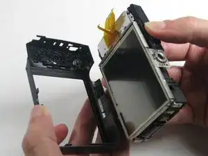
To reassemble your device, follow these instructions in reverse order.

Matt Mullins

Mitglied seit: 14/01/15

104 Reputation

Ein Kommentar

useless if you try to do it reverse.. Don't even try it.

The Heat -