Einleitung

This guide will involve complete disassembly of the camera.

  1. DNAR6XvqGNonBwfE
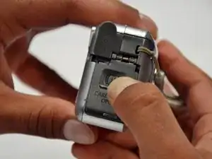
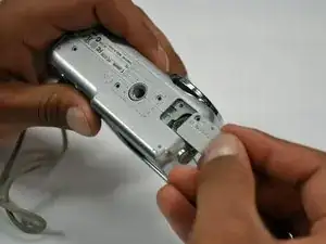
    • Slide the switch on the battery cover labeled "CARD/BATT. OPEN." to the right.

    • While still holding the switch, pull the cover down, allowing it to release and open.

  2. 2YcGZ2tQ3mQKy4np
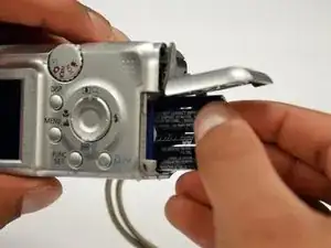
    • Tilt the camera slightly to allow the batteries to fall out.

  3. ZPgSTP2Dhh3YM4Ns
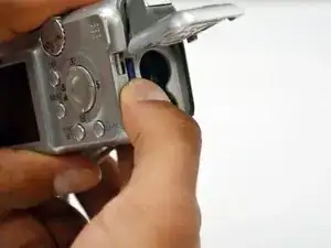
    • Press on and release the memory card to eject it.

  4. XxTrgvax1kcSdNtt
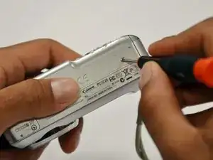
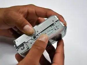
    • Unscrew the 5mm Phillips #00 screw from the bottom of the camera.

    • Make sure to keep the different size screws organized to make reassembling the camera simpler.

  5. 2ejiXXNIUoWULgrp
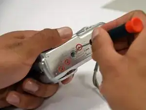
    • Unscrew the three 2mm Phillips #00 screws that are located on the bottom of the camera.

  6. 2nWDacX4nPHWZoCs
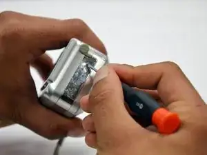
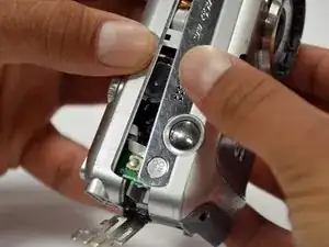
    • Remove the 4mm Phillips #00 screw that is located on the left side of the camera, if the display screen is facing you.

  7. WV3sAlkeAxSLWjVl
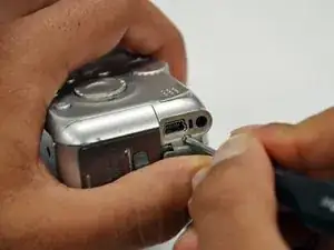
    • Take out the 4mm Phillips #00 screw under the rubber flap on the right end of the camera.

  8. Nhttgscad3GyBGxI
    Nhttgscad3GyBGxI
    HCg1XNinJxmQRcW2
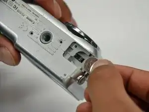
    • Remove the second battery cover on the bottom of camera.

    • Take the silver battery out of the camera.

  9. MlNOGqaONEgyjRQv
    MlNOGqaONEgyjRQv
    4ygPsP3Fh3cSsxR2
    ZuRKaEPYTEdTtKj1
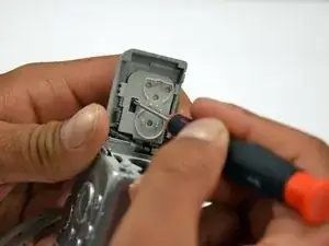
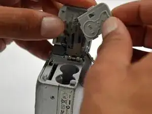
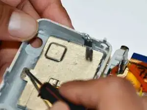
    • Remove the 4mm Phillips #00 screw on the inside of the flap that hides the battery and memory card slots.

    • Remove the light grey, plastic piece.

    • Remove the plastic portion of the battery flap cover. The metal piece will remain attached.

  10. sABWSYvRESqTUmu3
    sABWSYvRESqTUmu3
    dlATFvQSQ1qh2EWi
    JqJgifwiQWsNFTRG
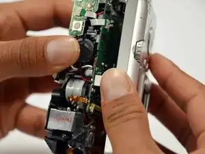
    • Slightly pull on each side of the camera. It should loosen up and come apart.

    • If it does not pull apart right away, use a little more force.

    • Do not give up!

  11. ZoYBQlq4CQGmAVPq
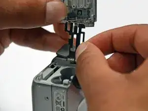
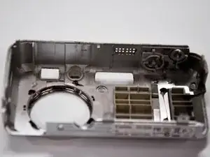
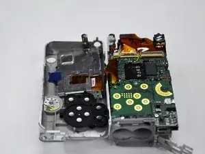
    • Remove the back case of the camera by pulling from the top.

    • Be careful when pulling off the case. There is a delicate gold ribbon connecting the bottom of the camera to the back case.

  12. 1kTi4OFEnuFPNxes
    • Remove the 4mm Phillips #00 screw from above the ribbon.

  13. kZGLSFobvhmcihYR
    • Gently peel off the blue tape on the top of the LCD screen.

  14. ivTPZCw6IdNYBqbl
    • Remove the 4mm Phillips #00 screw previously concealed by the blue tape.

  15. e4CoCNAZnvDAXqvZ
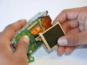
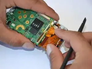
    • Gently lift the LCD screen off of the front casing by pulling up a tab on the side of the camera.

  16. N1ASITOkdFBIdQuM
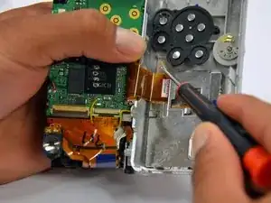
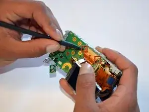
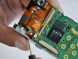
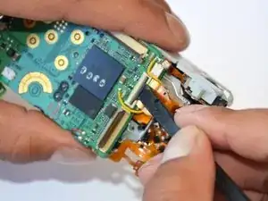
    • Using a spudger, lift the grey tabs to allow the ribbon to slide out.

  17. UDq6Dq1MN3TKwfoo
    • Since the tabs have been lifted, the ribbon should now slide out out easily.

    • Be careful not to distort the ribbon in any way.

    Thank you very much for the good knowledge that I can do by myself.

    K201

    Rachsuthee waiP -
  18. 6UStwLOSwkudJuFU
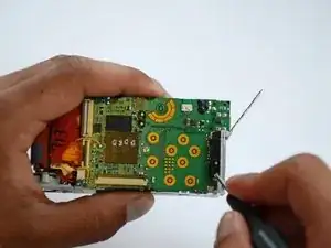
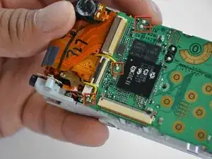
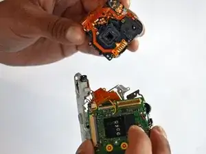
    • Remove the 5mm Phillips #00 screw located above the small black piece on the right side of the mother board.

  19. EqIVE3x4MyaNTDVE
    EqIVE3x4MyaNTDVE
    mHXir1BwcCTW6VlF
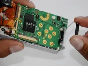
    • Remove the 4mm Phillips #00 screw at the bottom of the black piece.

    • Detach the black piece that the screws previously held in place.

  20. IfeoQ1M3Lia2jYER
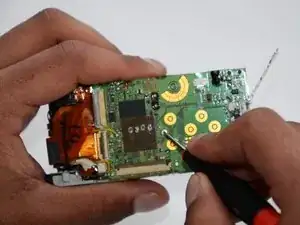
    • Remove the 5mm Phillips #00 screw in the middle of the motherboard.

  21. m2d4UVWNrxFRLwvM
    • Remove the 5mm Phillips #00 screw that holds the metal piece to the bottom of the camera .

  22. whxPeqjHvwMwPFyU
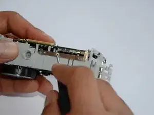
    • Remove the 5mm Phillips #00 screw that is located on the top of camera.

  23. UpsY4nUeVosScEfg
    • Remove the 2mm Phillips #00 screw that is located on the far left of the motherboard.

    • Be careful not to damage the multiple adjacent orange ribbons.

  24. dR1JhmaySYIaqyV2
    • Remove the 5mm Phillips #00 screw near the bottom left of the motherboard.

  25. ynHFDIumTYJAZrSv
    ynHFDIumTYJAZrSv
    KL4PkHa2Ldu4aWlw
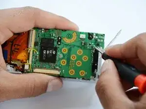
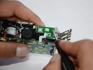
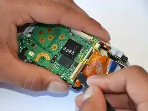
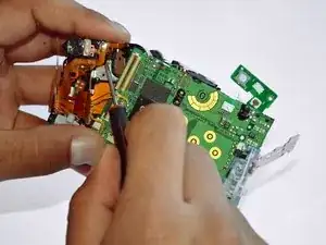
    • Using a spudger, unlock the locking mechanism that holds the lower orange ribbon in place.

    • Once unlocked, slide out the ribbon.

  26. IDG1fVWQGbRDAmvC
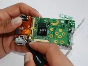
    • Using a spudger, unlock the locking mechanism that holds the upper orange ribbon in place.

    • Once unlocked, slide out the ribbon.

  27. hPVwfyAecp6Eb5ij
    • All that is required is to unsolder the few remaining wires. Then, the motherboard will be ready to be replaced!

  28. FOaEAbE3aZu5aHxA
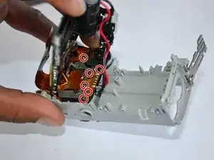
    • Remove the six 2mm Phillips #00 screws that are located under the motherboard.

  29. 5qW2wIu64Co5GVVQ
    5qW2wIu64Co5GVVQ
    DW5iL4Aw5pilXnQa
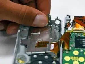
    • Remove the 4mm Phillips #00 screw that is located under the now disconnected top orange ribbon.

    • The lens piece can now be removed from the camera.

    каким образом определить какой винт откуда? под каждой фотографией свои винты и они не соответствуют

    Константин Дорофеев -
  30. iJTLGkrP3SUOkowp
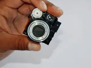
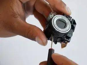
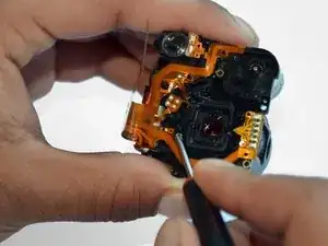
    • Remove the 5mm Phillips #00 screw on the back of the lens piece.

  31. iLThTKfjVOnA6TEM
    • Remove the 2mm Phillips #00 screw on the bottom of the lens piece.

  32. mZJvuIhaQCHQ6ufy
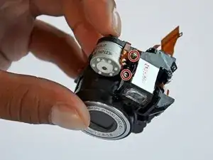
    • Remove the two 2mm Phillips #00 screws on the top of the lens piece.

  33. ChhZTZS5RS5gJYIA
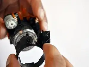
    • Gently slide off the black piece surrounding the lens. The lens is now disassembled!

Abschluss

To reassemble your device, follow these instructions in reverse order.

Tanner Coleman

Mitglied seit: 18/01/13

25 Reputation

Ein Kommentar

please put a big warning note on the step after removing the blue tape from the lens. and the next on is where you lift something on the mother board with a spluger..something like that. well i used a screwdriver and got such a big electrical shock.... scared the crapola out of me. please make a note .... can get electrical shock....

Gaby -