Einleitung

Use this guide to replace the Canon PowerShot A75's upper motherboard.

  1. TuwQuCgHNgNdjvt3
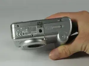
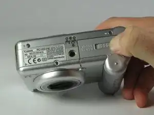
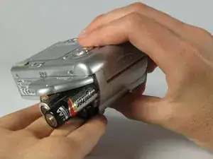
    • Turn the camera over and locate the "BATT OPEN" sliding switch.

  2. duIF4eWQCjCkYatW
    duIF4eWQCjCkYatW
    bLRxIvvAGKJxHVYH
    kD2lNcDXJJHqXfjK
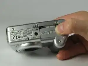
    • Slide the switch to the right.

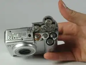
    • The battery cover should slide down and spring open.

  3. LovYTlKcJPLlNkIm
    LovYTlKcJPLlNkIm
    DPmurSWpIZ6VriwZ
    RfNGGVMw3XVWVQgV
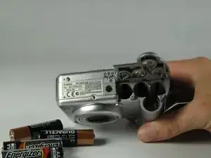
    • Remove the 4 AA batteries.

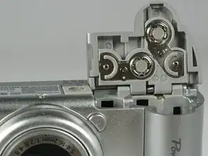
    • Watch for the orientation of the batteries as they slide out.

    • The battery orientation is shown under the battery flap itself and on a sticker next to the battery flap.

  4. tyRL1VdW6xpI2OqE
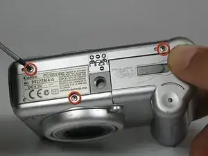
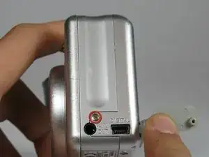
    • Remove the three 2.5mm screws on the bottom of the camera.

  5. Aa2TUmfa5BliHdqw
    • Remove the 3.8mm screw underneath the flap that covers the A/V port.

  6. KxSZAFD5UTKmQwLA
    KxSZAFD5UTKmQwLA
    6TiiKwLHnwpgscgX
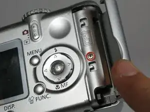
    • Remove the 2.4mm screw located underneath the cover of the memory card slot.

  7. qwFy1EGKfOtNOOBD
    qwFy1EGKfOtNOOBD
    wUOCmLAonkZDOkHt
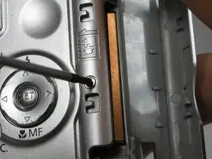
    • Open the memory card slot by sliding it laterally until you hear a click.

    • Remove the 5.9mm screw in the upper corner of the memory card slot.

  8. HqwKXCaRypyDny4E
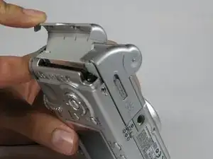
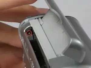
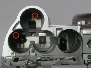
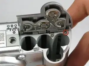
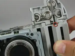
    • Remove the two 4.1mm screws at the bottom of the battery flap.

  9. OqRRyrgyjoRLPqZQ
    OqRRyrgyjoRLPqZQ
    JfSmRtTFUIfEDtGJ
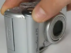
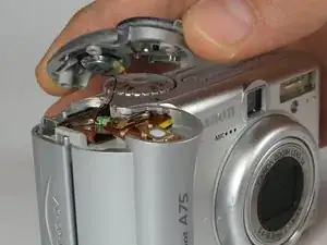
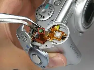
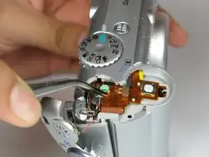
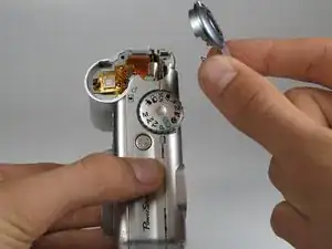
    • Lift the shutter button and speaker part from the top of the camera.

    • DO NOT pull the part too hard because there is a plug connecting the speaker to the camera.

  10. EHSDqfBZAgI5v3jR
    EHSDqfBZAgI5v3jR
    XPQNFAoPxF2sJtpa
    JD6nRmx61vWEmoUw
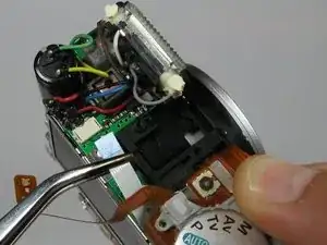
    • Using a pair of tweezers, grab the plug that connects the speaker to the camera and gently pull it out.

  11. 5IkKJwPK1RdHuVMO
    • Remove the rightmost 4.2mm screw underneath the battery cover, not the center screw.

  12. R3UJ1ZSblBhYkFPB
    R3UJ1ZSblBhYkFPB
    anplZX5EETSngbc2
    ujATG4VnLQsulwoq
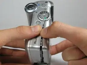
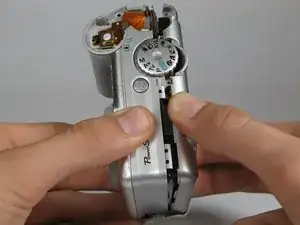
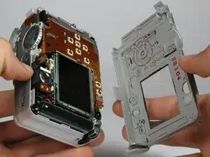
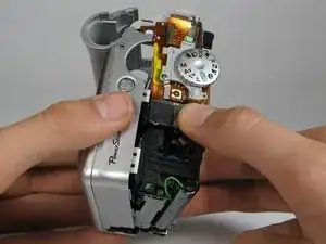
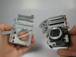
    • Separate the back casing and front casing of the camera using your hands.

    • Pulling the two halves apart can be difficult, especially at the top. Use a moderate amount of force.

  13. oKPRbEZ6DhaJfSD3
    oKPRbEZ6DhaJfSD3
    VVPnSiJXyCUWMNKZ
    eUCmPeKDgVTRMKYH
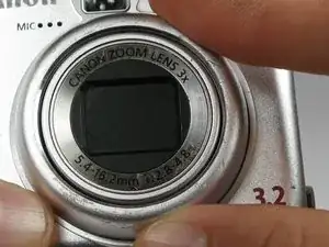
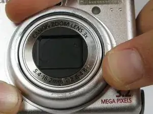
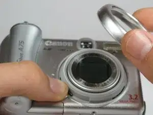
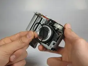
    • On the front of the camera, press the button on the lower left of the lens.

    • Twist the outer lens casing counter-clockwise and slide it out.

  14. xTmsUEKEiI1MsUUt
    xTmsUEKEiI1MsUUt
    NWTltvlFBwLC1QnA
    cD6STmpXXKVJOhdG
    • Take off the front casing.

    • There is a black rubber washer around the lens that comes out after you take the casing off. Make sure to replace it when putting the camera back together.

  15. vwibOBMk3LegleTs
    vwibOBMk3LegleTs
    XcXACkZGZOKanajp
    WVr2WNrsFC2lbJrO
    • Remove the 4.4mm screw directly behind the eyepiece on the top of the camera.

    • Remove the 4.3mm screw to the right of the eyepiece housing in the crack in between the eyepiece and a ribbon cable on top of the camera.

  16. aBAgoCgmKG16JWoP
    aBAgoCgmKG16JWoP
    M5nXUSWtJcXJaoQt
    64fldNTbfTkVmGv3
    • Gently wiggle the eyepiece out of its place. It should snap out of place.

    • There should be a white ribbon cable underneath attached to the motherboard.

  17. vA33GEfhBAK1e4lP
    vA33GEfhBAK1e4lP
    WBVQr4NKCRNQesLC
    m1HO4VNOGeAdV5FE
    • Locate the white cable on top of the camera where the eyepiece was.

    • Using tweezers, grasp the white cable as close to the connection point as possible and gently remove the cable.

    • The cable should just slide out with a slight tug.

    • Remove the 2.9mm screw directly underneath the white cable.

  18. kOHZC2skAYGgPKpx
    • Remove the 4.2mm screw directly under the battery flap.

  19. uApBpWHMeiiVgAeF
    uApBpWHMeiiVgAeF
    B6nV1iTMVqFdlHP6
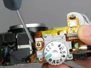
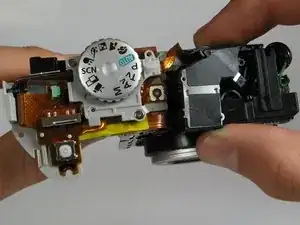
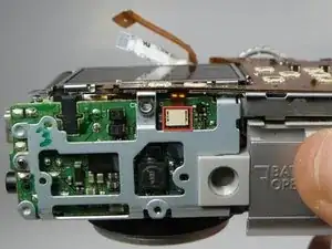
    • Remove the 3.4mm screw inside a deep hole on the back copper panel beneath the circular mode switcher.

    • This screw is a little difficult to get out.

  20. dlH4d6YUXiZGvXKt
    • Remove 2.5mm the screw in the silver housing on the bottom of the camera. This screw is holding the back panel in.

  21. IP5YPJb3gyRSISIo
    IP5YPJb3gyRSISIo
    3Os4rxkLpSnGKsGL
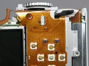
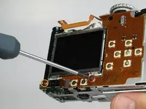
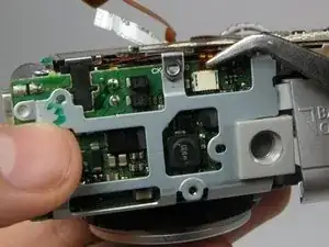
    • Remove the 3.4mm screw near the bottom of the back face of the camera on the copper ribbon.

    • Remove the 2.9mm screw on the back face of the camera in the bottom left corner.

  22. XfPmB2biLBm5SkC3
    XfPmB2biLBm5SkC3
    YF4y3JhuLkeSaeUT
    noBpj6Cv6UjacigD
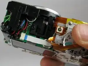
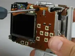
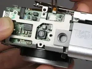
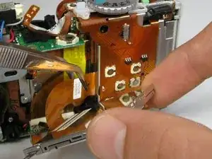
    • Locate the copper ribbon cable attaching the LCD screen to the bottom motherboard.

    • Grasp the cable near the white connector and gently remove the cable.

  23. oYUBKnyD4GucMd5l
    oYUBKnyD4GucMd5l
    ZofQH6vEjmcgiZZ6
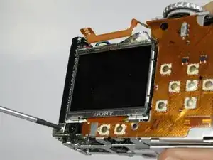
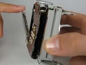
    • Gently pull back the LCD screen to around 45 degrees from the back of the camera.

    • Do not pull the back panel too far, it is connected to the top of the camera with ribbon cables and is not meant to separate from the camera.

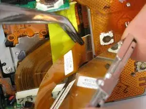
    • Locate the larger ribbon cable connecting the screen to the body of the camera.

  24. 2kvQdtkQItY6EEWg
    2kvQdtkQItY6EEWg
    XfIVITVLbTJfYIKL
    SCDXJtsCgbiITDEd
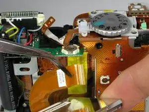
    • Gently grasp and pull the cable from the motherboard. The cable should easily slide out.

    • This ribbon cable may be easier to remove using your hands instead of the tweezers.

    • The LCD should now be out after the cable is removed.

  25. hICeHBOEJLACFj1B
    hICeHBOEJLACFj1B
    6qQGS2ePMeHqAfAv
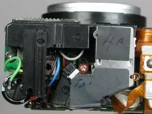
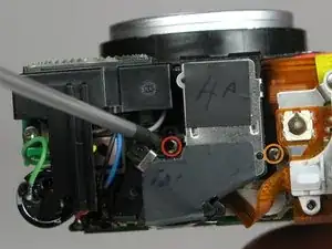
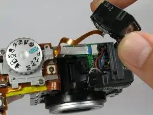
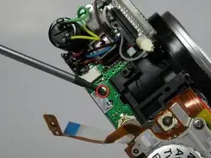
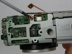
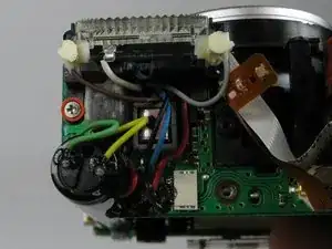
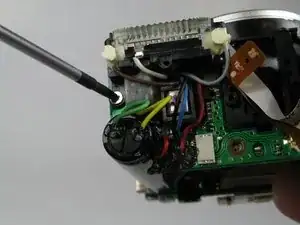
    • Remove the 3.5mm screw found near the capacitor and the flash unit.

  26. SuaxTkwgClmAJnJW
    SuaxTkwgClmAJnJW
    2mlRmyGWZvoGNBI6
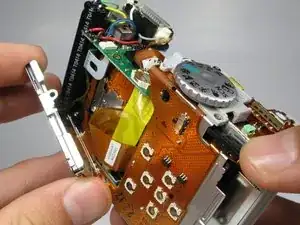
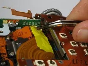
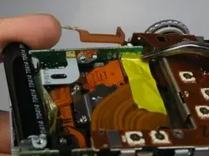
    • Carefully remove the yellow piece of adhesive tape connected to the motherboard.

  27. oE2joK2BkWuT23A6
    oE2joK2BkWuT23A6
    JQDcMcViEBDVpIo6
    QlNbBlYTGLbLxowZ
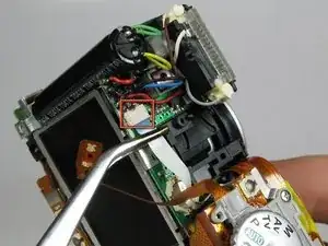
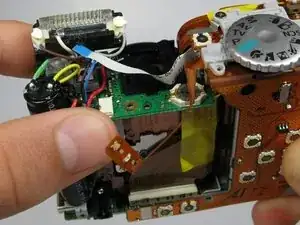
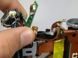
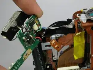
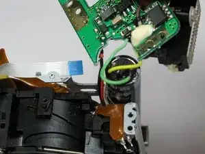
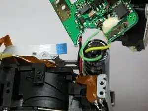
    • Remove the main motherboard from the casing, which is connected to the flash unit, capacitor, and bottom motherboard.

    • Do not damage or remove the cables connected to the motherboard. The motherboard is connected to the bottom motherboard by two wires. There are also two red wires on the outside of the motherboard.

  28. c33uIL4nWu1NKNLC
    • Do not proceed to the next step unless you have previous soldering experience because you can damage the motherboard if you are not careful.

    • Unsolder any remaining wires on the motherboard to completely remove it.

Abschluss

To reassemble your device, follow these instructions in reverse order.
Carlos Fletes

Mitglied seit: 18/04/12

1 Reputation

0 Kommentare