Einleitung
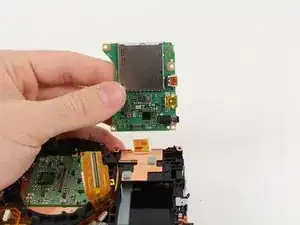
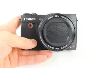
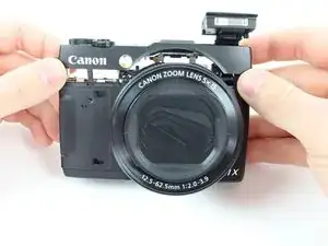
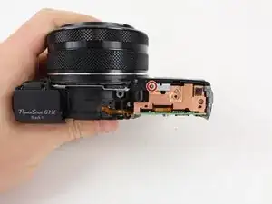
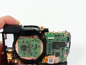
Use this guide to replace the motherboard of your camera. Motherboard replacement may be necessary if the buttons on your camera are not working or if there are other major malfunctions with the way your camera is functioning.
Werkzeuge
-
-
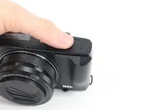
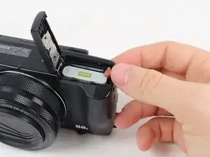
Locate the battery housing cover on the bottom of your camera.
-
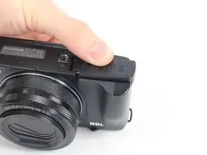
Place a finger on the textured portion of the battery housing cover.
-
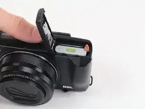
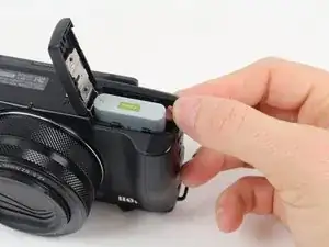
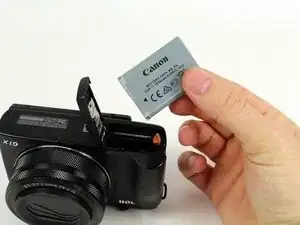
Slide the cover in the direction that the arrow is pointing.
-
-
-
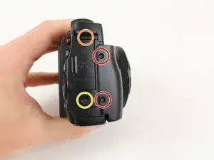
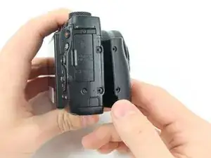
Remove the two 4mm Hex screws that connect the grip to the camera with a Hex head screwdriver.
-
Remove the two Phillips screws to the left of the hex screws with a Phillips head screwdriver:
-
One 2mm screw
-
One 3mm screw
-
Remove the grip from the front of the camera by pulling it away from the lens and then away from the camera.
-
-
-
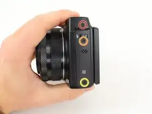
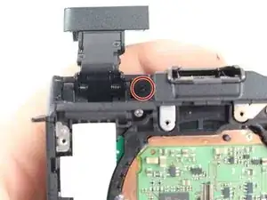
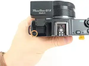
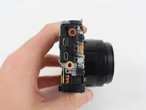
Remove the following three Philips screws from the flash release side of the camera with a Philips Head screwdriver:
-
One 2.5mm screw
-
One 4.5mm screw
-
One 1.75mm screw
-
-
-
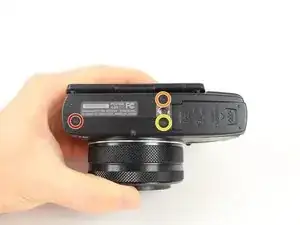
Remove the following three Philips screws from the bottom of the camera with a Philips Head screwdriver:
-
One 3.25mm screw
-
One 2.5mm screw
-
One 2.75mm screw
-
-
-
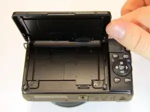
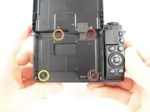
Remove the following four Phillips screws securing the back panel with a Philips Head screwdriver:
-
Two 3 mm screws
-
One 2mm screw
-
One 2.5 mm screw
-
-
-
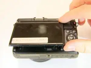
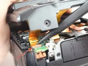
Use a plastic spudger to gently release the locking tab holding the ribbon cable, closest to the edge of the camera, in place.
-
Repeat this process for the second ribbon cable to the right.
-
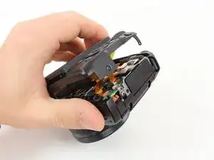
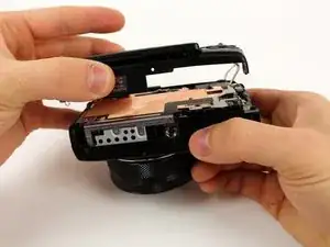
Carefully lift the back casing away from the camera.
-
-
-
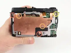
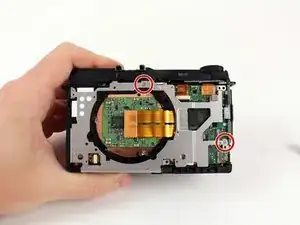
Remove the five Phillips screws that are attached to the copper plate with a Philips Head screwdriver:
-
Two 3mm screws
-
Two 1.5mm screws
-
One 4mm screw
-
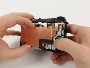
Lift the copper plate away from the camera.
-
-
-
Remove the following three Phillips screws securing the silver plate with a Philips Head screwdriver:
-
Two 2.9mm screws on the front of the camera
-
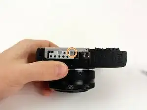
One 1.8mm screw on the bottom of the camera
-
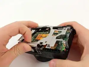
Lift the silver plate away from the camera.
-
-
-
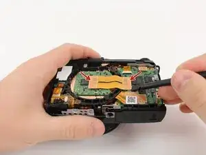
Use the plastic spudger to lift up both sides of the ribbon cable from its connector pins.
-
-
-
Use the flat end of the plastic spudger to rotate the black plastic locking tab towards the ribbon cable.
-
Insert the pointed end of the plastic spudger into a small hole on the side of the ribbon cable and pull the ribbon cable out of its housing.
-
Use the flat end of the plastic spudger to pry the ribbon cable connector from the motherboard.
-
-
-
Remove the following two Phillips screws from the flash cavity with a Philips Head screwdriver:
-
Remove the 2mm screw to the right of the flash.
-
Remove the 2.5mm screw to the left of the flash.
-
-
-
Remove the 2.5mm Phillips screw from the front plate with a Phillips head screwdriver.
-
Pull up on the top portion of the camera to separate the top casing from the camera body.
-
-
-
Remove the 3.5mm Phillips screw from the grey tab on the top of the camera with a Philips Head screwdriver.
-
Rotate the camera so the back panel is facing you.
-
Remove the 1.4mm Phillips screw from the sliver tab near the top of the camera with a Philips Head screwdriver.
-
-
-
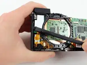
Use the flat end of the plastic spudger to release the plastic retaining clip on the side plate closest to the lens.
-
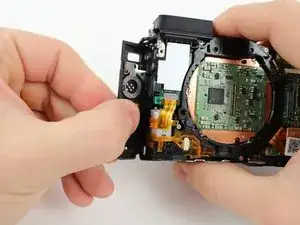
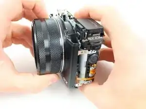
Rotate the side plate closest to the lens toward the lens of the camera and then pull the plate away from the camera.
-
-
-
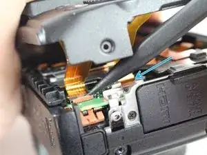
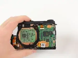
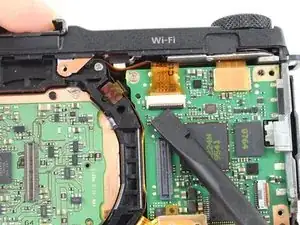
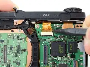
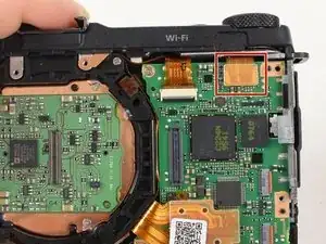
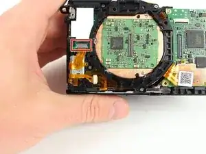
Release the plastic locking tab of the upper ribbon cable with the plastic spudger.
-
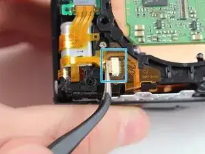
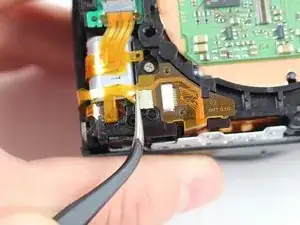
Pull the top ribbon cable from its mount with the fine tip metal tweezers.
-
Remove the bottom ribbon cable with the fine tip metal tweezers by pulling it toward the flash switch side of the camera.
-
-
-
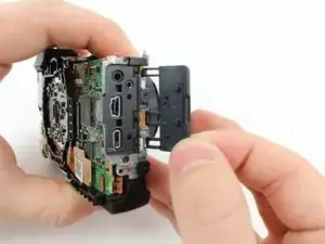
Remove the rubber dust cover from the camera by moving the hooks away from the three prongs holding them in place and then pulling the cover away from the camera.
-
-
-
Remove the following two Phillips screws from the side of the camera with the three connector ports with a Phillips head screwdriver:
-
One 2.5mm screw
-
One 3.3mm screw
-
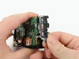
Pull the metal shield away from the camera.
-
-
-
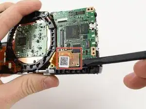
Use the plastic spudger to remove the ribbon cable from the motherboard by placing the spudger under the ribbon cable connector and pulling up.
-
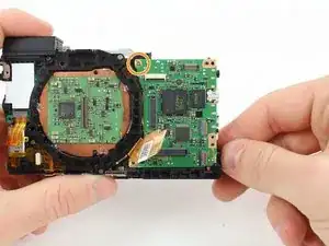
Remove the 2.8mm screw from the motherboard.
-
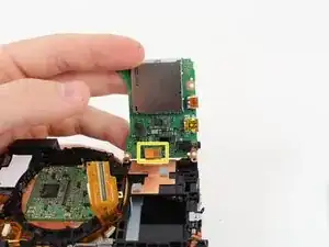
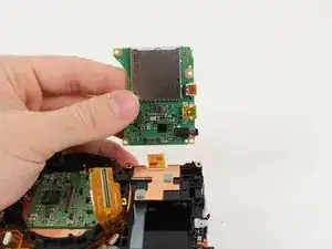
Carefully rotate the motherboard upward.
-
Use the plastic spudger to remove the ribbon cable from the bottom of the motherboard by placing the spudger under the ribbon cable connector and pulling up.
-
To reassemble your device, follow these instructions in reverse order.
