Einleitung
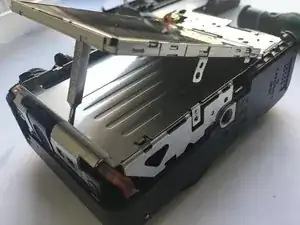
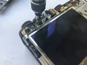
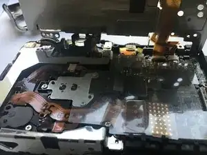
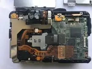
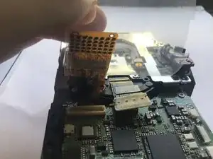
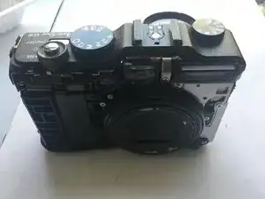
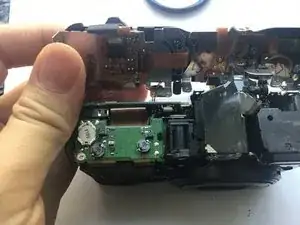
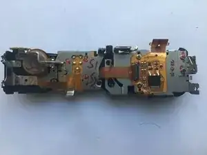
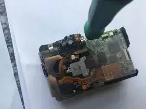
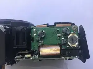
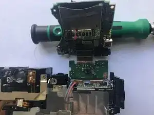
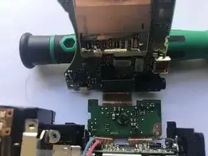
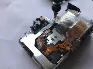
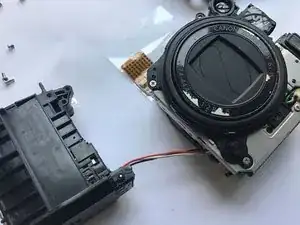
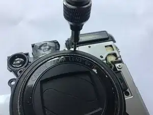
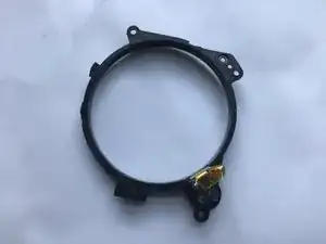
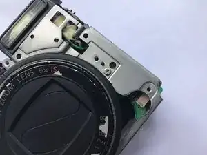
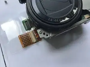
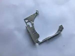
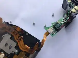
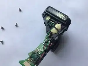
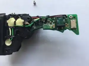
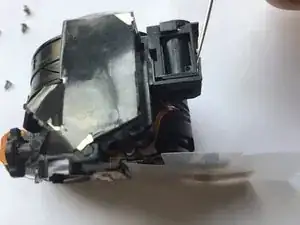
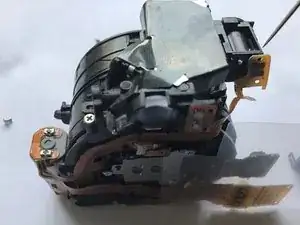
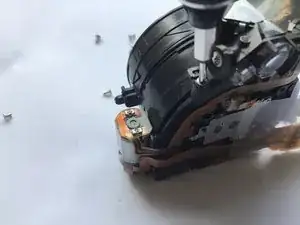
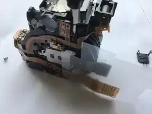
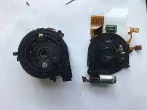
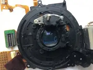
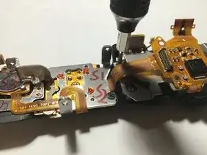
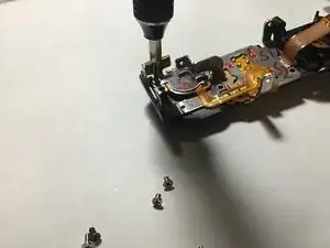
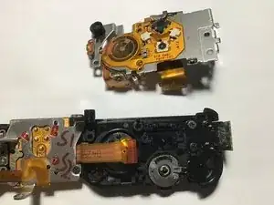
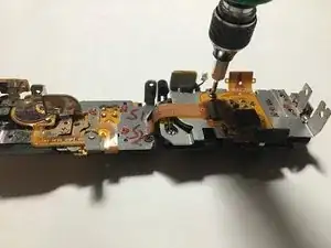
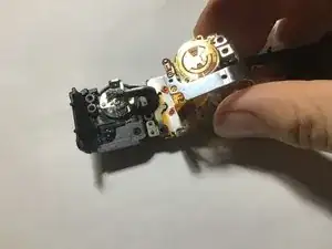
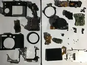
Continues the previous disassembly, this guide aim to disassemble the “physical” part of the camera.
Warning: Following this guide may expose you to voltage. Exercise caution when following this guide.
Werkzeuge
-
-
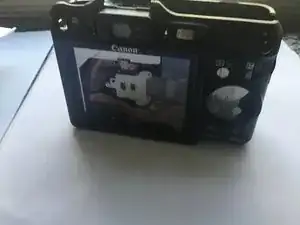
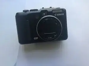
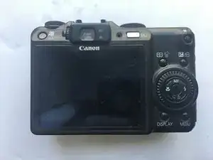
The Canon PowerShot G9 made its debut around 2007. With 12.1 mega pixels and 3200 ISO, it's easily one of the more economical choice for amateur and hobbyists.
-
I mean, after 10 years it's still pretty good. The 12.1 mega pixel is more than needed, coupled with a 6x optical zoom to take sharp photos of everyday objects.
-
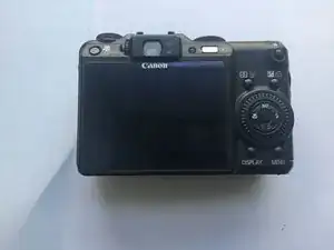
It got a few scuffs and maybe some dings and some paint scraped off (or it fell off on itself) but it's still very capable.
-
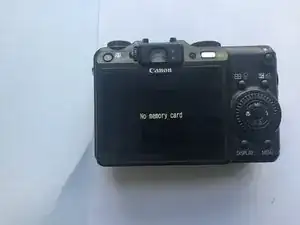
And yep, I did took out that 10 year old SD card. A miracle that it still works after a trip to the washing machine.
-
-
-
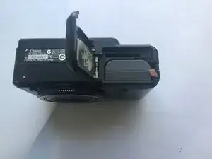
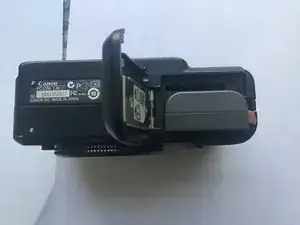
For starters, we'll pop out that battery.
-
And the SD card, if you had not done that already.
-
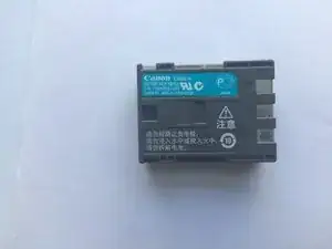
The battery tolls in a good 720mAh @ 7.4 V with a capacity of 5.3Wh.
-
And ... there is a battery-eliminator for the G9 if you happen to take lots of photos indoors. Proof? A trap-door like mechanism on the side of the battery compartment -- for the wires to go in and out.
-
-
-
We'll start
attackingremoving the screws on the outside of the machine. -
Which tolls in at ... 6?
-
I'm not sure if there are screws around the mounting point (for the camera tri-pods). I don't have it on my unit ...
-
I know there will be a LOT of screws, so prepare some
food container... containers.
-
-
-
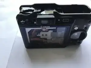
The screws free up the rear ...
-
Case? Panel? Cover?
-
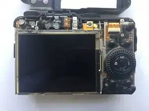
Which reveals a giant screen and ... some really delicate flex cables.
-
Let's start by removing the screen ....
-
Which have its flex cable trapped under the controls.
-
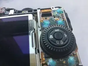
So let's start removing the buttons for now ...
-
-
-
And ....
-
BOOBY TRAP!
-
Flick the board on its long sides out. Some of it may be snagged under the top ribbon cable, so do it carefully.
-
-
-
So this part would be empty.
-
There will be a screw on the bottom holding down the display, so you will unscrew that ...
-
And then you would push the screen toward the bottom of the camera with your fingers.
-
And then the screen will ....
-
???
-
The flex cable had still a long way to go before being "free". Apparently we would need to remove the steel brackets ...
-
-
-
Or you can try to lift the screen up ...?
-
Nothing's there. Brackets are the go-to.
-
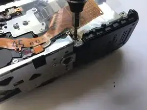
You'll need to remove this screw ...
-
Which frees up this interesting button + roller combo.
-
-
-
You will need to remove the screw below the buttons board too...
-
And THAT will give clear the entire screen (and buttons) assembly.
-
Flick the entire assembly upward and detach the other ribbon cable.
-
Display backlight? I can't figure out another use for that two-lane.
-
-
-
So this is how the camera looks like ...
-
I'll DEFINITELY leave that for later. Look at that flex cable. It had a scary amount of connection AND test point.
-
So what are we here to do? We are supposed to remove everything, which includes the motherboard, and then I'll take apart the lens and clean its insides and outsides. Or I think I am going to do that.
-
-
-
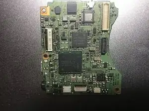
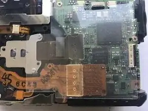
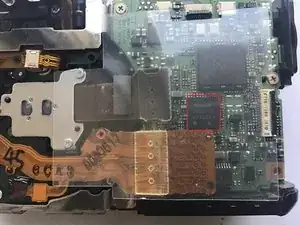
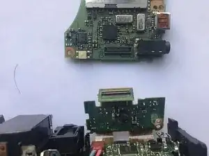
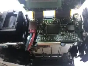
We had this ELPIDA DDR3 RAM HB0010A17EE for ... shots buffers?
-
Which is overlaid on ... a processor?
-
We had the Sony D4807GA823DG4V
-
15019GB 7MR4G 07G
-
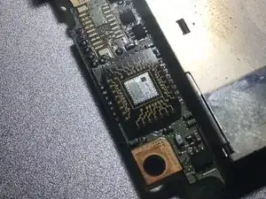
We had a unnamed IC and another ... IC on the front. But hey ... this one on the back is REALLY eye-catching. A exposed-die processor!
-
Could this be the GPU?
-
-
-
And to remove the motherboard, we will need to remove the top assembly (which appears to be a single large piece) which requires removal of the front ...
-
Cover? Panel? Plate?
-
Start by prying near the TOP of the front plate. There is a plastic tab holding it.
-
Hello .... how are you doing there?
-
-
-
And then we'll go remove the upper assembly ...
-
You have this screw at the back ...
-
You had this screw on the front ... took me a while to figure it out.
-
And you had this screw on the right.
-
THAT one. The top one.
-
-
-
And ...
-
BOOBY TRAP!
-
Sadly, this is largely how it would be done. That tiny connector is for the microphone on top of the machine, near the function wheel.
-
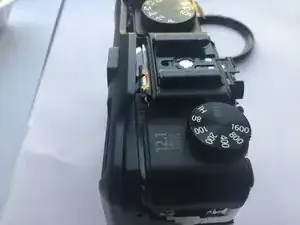
Look at that assembly! It's absolutely monstrous -- the numerous dials, the power button, the playback button, the hot shoe ...
-
Some of which looks unnecessarily delicate, but hey, these are dials. Non-digital dials that use physical contact on every single click. And the copy-paste button (that's how I call it) had its own light.
-
-
-
So, what do we have next?
-
Clearly you can't take out the power boards without the motherboard first.
-
So let's go do that. But heeeeyyyy....
-
What is Sony doing here?
-
Anyway. Let's remove this screw ....
-
And that screw(Far right).
-
-
-
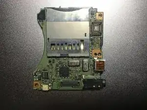
And this screw on this weird ... "interconnect" board that houses a ...
-
RTC battery?
-
And flip the entire thing out ...
-
-
-
So how exactly on earth should I do to remove these stuff without snagging a single copper line on these flex cables?
-
Answer: inter-board connectors.
-
BOOM! You're out.
-
Which leave us with this power board ...
-
Apparently the power is directed to the entire "system" part through this single connector, so the board is free to move after the screw is removed ...
-
-
-
Now, after careful observation I cannot find significant exposed areas of high voltage.
-
Perhaps as we progress we will able to figure something out.
-
-
-
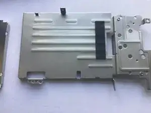
Begin that by removing this metal bracket.
-
Let's free these few screws ...
-
The ones one the front too. Don't forget about them.
-
-
-
The lens assembly should now separate from the ...
-
Body. Let's just call it by that.
-
We had this pesky connector to deal. Ughhhhhh...
-
-
-
Removal of metal bracket require the removal of the ... accessory lock ring.
-
Which require the removal of the decorative accessory lock ring. Remove that first.
-
-
-
Let's wedge this hot potato out of this place!
-
Canon had done a very good job insulating the circuit on the top half.
-
The wires lead to solder joints on the board, which are exposed.
-
Perhaps the different lights require different voltages and this one is more docile. or ... perhaps the circuit is only charged when a flash is imminent
-
-
-
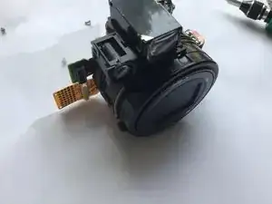
Now this is what I am left with ...
-
This is very intricate and delicate equipment. I can hardly see a single screw here either ...
-
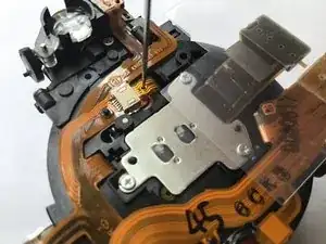
Let's pick at it ...
-
Literal. These things are so tiny and fragile, anything (including those prying tools) will probably bend them too far (and break them).
-
So let's grab a needle ...
-
Start with connectors? I mean I can't see anything else ...
-
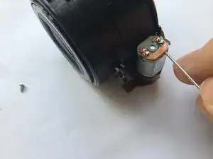
Ah, this motor. Spring contacts too. Wonder if they still had these today.
-
-
-
Pick pick.
-
Eeeeeeekekkkkkk....
-
Pick pick pick.
-
Pick.
-
Here comes the LED thing!
-
I am surprised. I thought the entire thing would be a entire unit. Guess it won't matter to loose a tiny bit of precision here -- it just illuminates the area for autofocus.
-
-
-
Screw screw.
-
Screw. Screw screw screw.
-
Ahh... this one is of fancy.
-
Just why are there this many dust inside?!
-
-
-
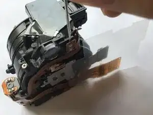
Ok. now we need to remove the motor thingy ...
-
Pick pick.
-
Here is a screw ...
-
Hmmmm....
-
Pick.
-
-
-
Hello.
-
Fine. But I can't really find a way in.
-
Plus, this is a disassembly. And I need the camera back.
-
Let's sweep the dust off the CCD (they came in via gaps between it and the camera internal, which gets the dust from the other holes of the camera (e.g. gap between viewfinder lens).
-
-
-
I do expect a little more of these switches ... they are currently just customized brushes on top of customized PCB ...
-
At least these are operating on low voltages and current, otherwise the entire thing will be filled with oxidation marks and black gunk.
-
But let's face it -- that shutter button is pretty cool, in any case.
-
-
-
DISASSEMBLY COMPLETE!
-
Enjoy piecing this little thing back together ... just don't introduce more dust to it.
-
To reassemble the device, follow the guide in reverse order.
