Einleitung
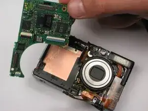
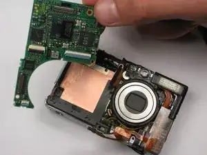
This guide shows the user how to take out the logic board, and therefore have the opportunity to replace a defective board.
Werkzeuge
-
-
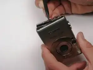
Unscrew the six screws on the casing. Two are on the bottom as pictured; two more are on each side of the camera.
-
-
-
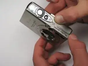
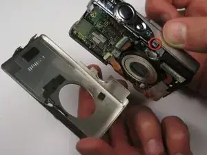
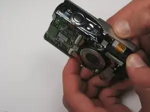
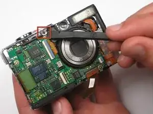
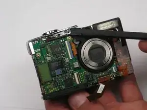
Find the line that separates the casing into its two halves. Hold each half separately, and gently pull apart.
-
Note that there is a small metal clip holding the two halves together. It might help to press down on the back half (indicated) while pulling upward slightly on the front half.
-
-
-
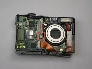
Remove the square, clear, rubber protector from the front of the logic board. This is not necessary to remove, but can easily fall off and get lost during later steps.
-
-
-
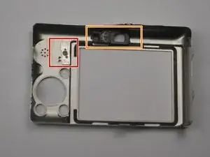
When you reassemble the camera, make sure the switch on the casing matches the position of the switch on the camera internals.
-
The black viewfinder padding can easily fall off the casing. Make sure you don't lose it when moving around parts.
-
-
-
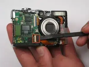
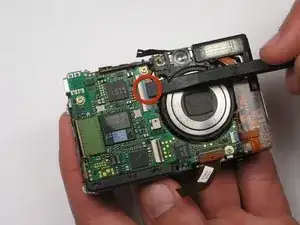
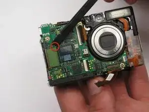
Remove the LCD cable by gently prying the hinge open with a spudger or your finger. The cable should easily slide out.
-
-
-
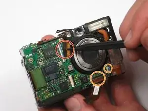
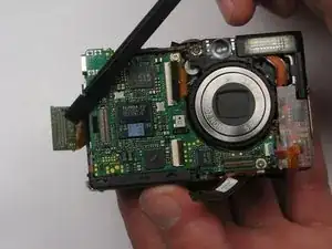
Pull the ribbon out of the socket using the spudger or your finger.
-
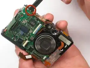
Disconnect the two other ribbons from the logic board in the same fashion.
-
-
-
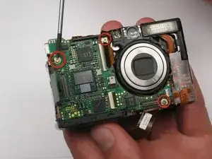
Use the screwdriver to remove the three screws on the logic board. Take note that the bottom right screw is shorter than the other two.
-
To reassemble your device, follow these instructions in reverse order.
