Einleitung
This guide will take you through the process of replacing a broken screen on a Canon PowerShot SX120 IS.
-
-
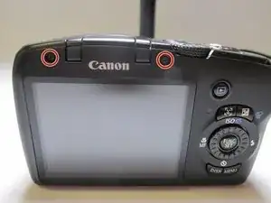
Turning the camera so the screen is facing you.
-
Remove the two black 3.4 mm screws with a Phillips #00 screwdriver.
-
-
-
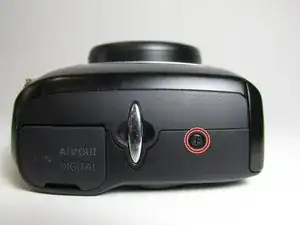
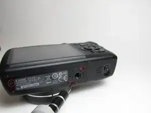
Put the camera with the lens facing up and turn it to the side so the DC IN A/V OUT DIGITAL is facing you.
-
Remove the single black 3.4 mm screw with a Phillips #00 screwdriver.
-
-
-
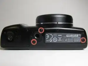
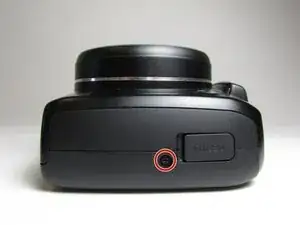
Put the camera with the lens facing up, and turn it to the side where the battery cover is located.
-
Remove the three black 3.4 mm screws with a Phillips #00 screwdriver.
-
-
-
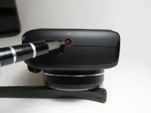
Put the camera with the lens facing up, turn it to the side where the compartment of the battery (CR1220) for time/date is located.
-
Remove the single black 3.4 mm screw with a Phillips #00 screwdriver.
-
-
-
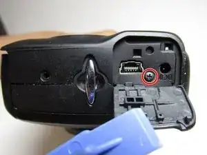
Put the camera with the lens facing down, and turn it to the side where the DC IN A/V OUT DIGITAL cover and the silver lanyard attachment are located.
-
Open the DC IN A/V OUT DIGITAL cover.
-
Remove the single black 3.4 mm screw with a Phillips #00 screwdriver.
-
-
-
Turn the camera with the lens facing down.
-
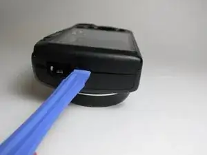
Use the iFixit opening tool to make leverage. Insert the opening tool in the seam where the front case and the back case assemble.
-
Carefully put pressure on the opening tool so the cover can gradually open.
-
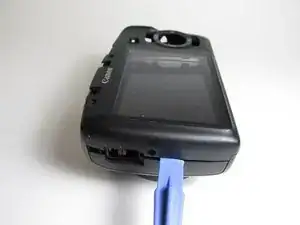
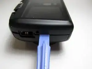
Slowly slide the opening tool along the gap and around the edge of the camera.
-
-
-
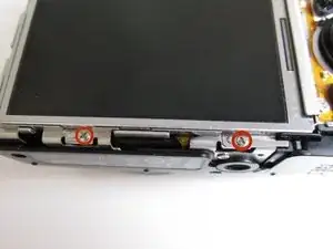
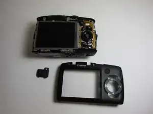
Remove the two screws that are attached directly below the screen with a #000 philips screw driver. These screws secure the screen to the main frame of the camera.
-
Remove the two 3.4 mm screws
-
-
-
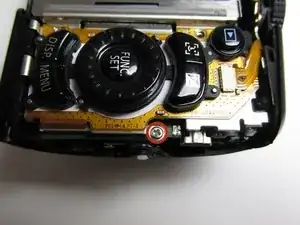
Place the camera with the lens facing down. Find the screw that is located on the right side of the camera next to the function set button.
-
Remove the 3.4mm screw with a #000 Phillips screwdriver.
-
-
-
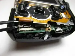
Leave the camera facing down and locate the ribbon connector. The ribbon connector is placed bellow the main button panel on the bottom right side of the camera.
-
Lift the main button panel and gently hold the ribbon connector with the black tweezers.
-
Once the ribbon has been entirely disconnected, lift the entire panel and place it above it's original positions. The panel will not be entirely removed only the lower half.
-
-
-
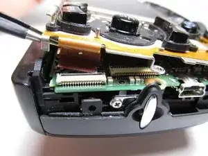
Place the camera with the lens facing down.
-
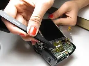
Use the black tweezers to gently begin to lift the screen. Begin lifting the screen from the left side.
-
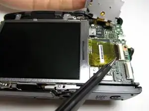
Locate the ribbon connector that is attached to the screen and also the motherboard.
-
Remove the ribbon from the motherboard connection by flipping up the small black clamp on the connector with a spudger.
-
To reassemble your device, follow these instructions in reverse order.
Ein Kommentar
between step 8 and step 9 you need to remove 2 screws on the right side of the screen.
vera -