Einleitung
This guide will guide you through replacing the motherboard/ circuit board in your Canon Powershot SX150 IS. This will help you fix any major issues with the camera function, if there seems to be no problems with the other hardware.
Werkzeuge
Ersatzteile
-
-
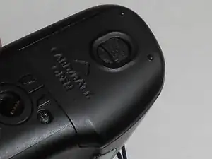
Locate the battery cover on the bottom of the camera.
-
Slide the battery compartment cover the direction the arrow is pointing to open the compartment.
-
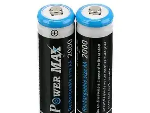
Remove batteries.
-
-
-
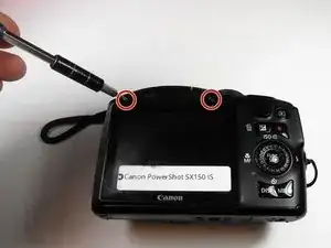
Remove the two 5mm screws from the side of the camera with the J000 head screw driver.
-
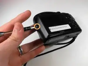
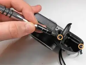
Using the same screwdriver, remove the one 5mm screw from the other side of the camera located under the A/V Out flap.
-
-
-
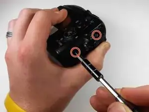
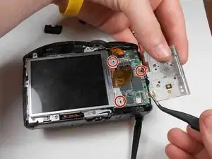
Remove the three 3mm screws using the size J000 screw driver from the button plate.
-
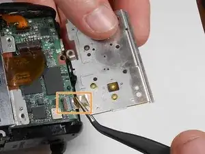
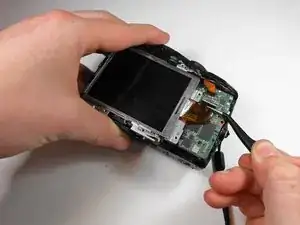
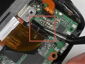
Gently flip up the flex ribbon lock and remove the flex ribbon using tweezers.
-
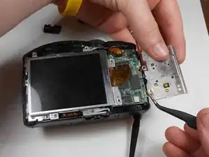
Move the button plate out of the way.
-
-
-
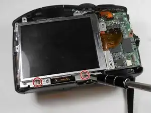
Remove the two 2mm screws from the bottom of the screen with the size J000 screw driver.
-
You can then lift the screen out of place and set it aside.
-
-
-
With the J000 Philips head screwdriver, remove the two 2mm screws from under the flash.
-
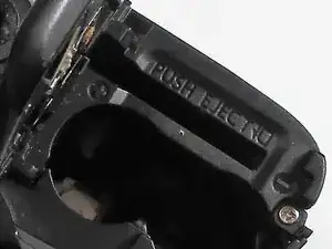
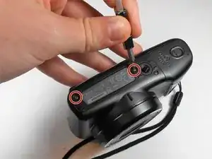
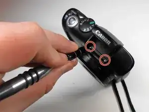
Using the same screwdriver, remove the two 5mm screws from the bottom. One is under the battery door.
-
With the same screwdriver, remove the 2mm screw at the top of the metal plate.
-
-
-
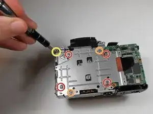
Using the J000 Philips head screwdriver, remove the four 7mm screws from the silver panel.
-
Remove the two 5mm screws.
-
Remove the one 3 mm screw.
-
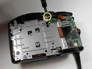
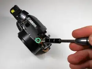
Using the same screwdriver, remove the 3mm screw from the top of the camera.
-
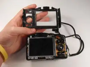
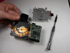
Pull the panel off and set it aside.
-
-
-
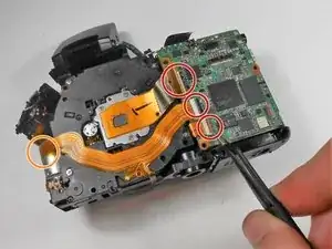
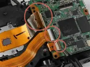
The green-colored circuit board is connected to the camera with a total of four flex ribbons.
-
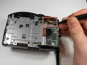
The three flex ribbons on the right have locking latches that need to be unlatched before removing flex ribbons. Unlatch all three latches and then remove flex ribbons using tweezers.
-
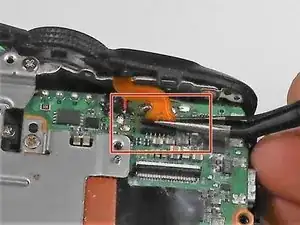
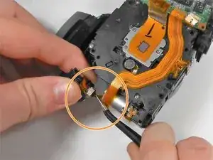
The fourth flex ribbon needs to be carefully unplugged using tweezers.
-
Once all four flex ribbons are unplugged the green motherboard is free for removal.
-
To reassemble your device, follow these instructions in reverse order.
Ein Kommentar
This procedure is bogus. It's more or less ok until the last step: "Once all four flex ribbons are unplugged the green motherboard is free for removal." WRONG! The mainboard is still connected to the battery case, flash module and cmos battery with wires soldered to it. Good luck with that unless you're an expert solderer. I got sucked in thinking I could swap the mainboard from a for-parts sx150is into one with a flakey USB port. Waste of time.
Very useful information and pictures, although with a couple of omissions noted in the comments. (Kind of like getting a recipe from your favorite chef who always seems to leave out one or two of the key ingredients.)
Eventually, if you go slowly, you will get all of the screws out. Just take pictures or make a drawing as you go along so that you know which screws go where when you reassemble. I learned quite a bit about what makes this lens jam and may not have to go quite so deep in to the camera the next time I’m trying to fix a jam.
Phil Smith -