Einleitung
The PowerShot A720 is an A-Series camera that features an 8.0-megapixel resolution, high-power 6x optical zoom and is powered by 2 AA batteries. Images are stored on SD memory cards.
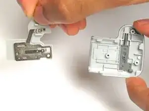
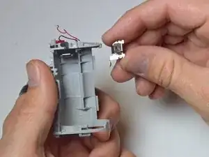
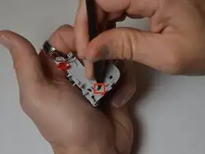
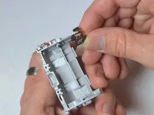
This guide provides a step by step instruction on how to replace the battery contacts if the batteries will not power the camera.
Before using this guide, inspect the contacts for corrosion or other reasons the camera is not powering up.
Be sure to remove the SD memory card before replacing the battery contacts.
Werkzeuge
-
-
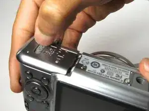
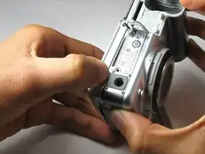
Turn to the bottom of the camera to access the battery department door.
-
Push the battery lock up to open.
-
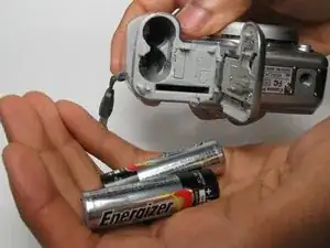
Slide the batteries out of the camera.
-
-
-
Place the camera on a flat surface so that the lens is facing up.
-
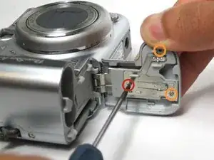
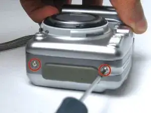
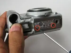
Use the Phillips #00 precision screwdriver to remove the innermost 4 mm Phillips head screw. Remove the door from the camera.
-
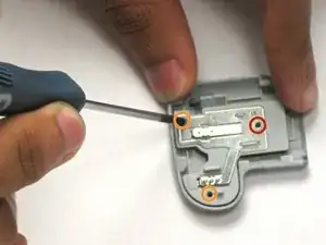
Place the door on a flat surface with the battery contact facing up. Remove the two 4 mm Phillips head screws.
-
Slide the battery contact from the door.
-
-
-
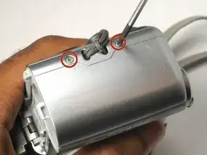
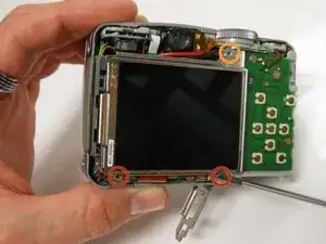
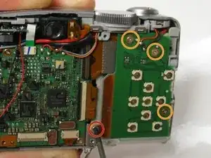
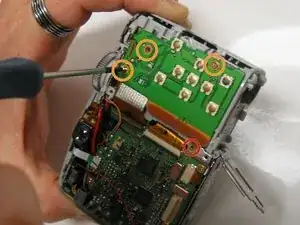
Unscrew the two 3 mm screws that are below the LCD screen mount.
-
Unscrew the top 4 mm screw.
-
-
-
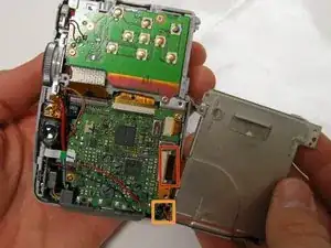
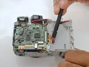
Carefully lift and turn over the LCD ccreen to see the motherboard.
-
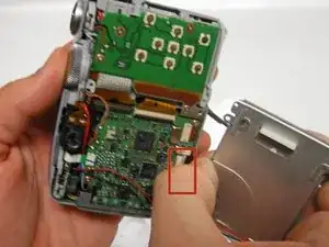
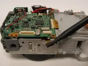
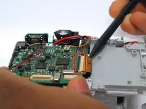
Carefully disconnect the LCD screen ribbon cable away from its ZIF connector with your thumb and index finger. Make sure to have your thumb and index finger cover as much of the ribbon's width and as close to the ZIF connector as possible without touching the motherboard while pulling the ribbon out.
-
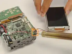
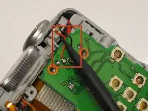
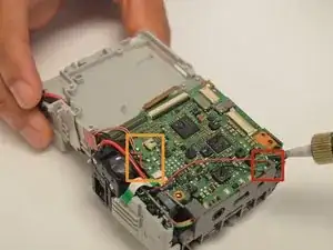
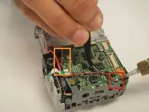
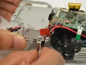
Use the soldering iron to separate the black and red power wires from the motherboard.
-
-
-
Remove the 3 mm Phillips head screw that is between the circuit boards.
-
Remove the next three 3.5 mm Phillips head screws that are on the button circuit board.
-
-
-
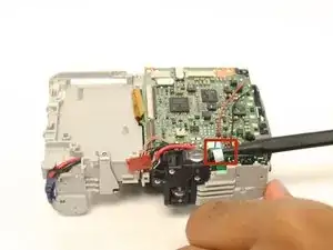
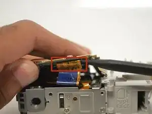
Use the spudger to unclip both wires from underneath the shutter button and settings dial housing unit.
-
-
-
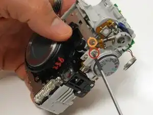
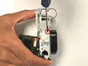
Turn the camera over and unscrew 4.5 mm Phillips head screw to detach the shutter button and settings dial from the rest of the camera.
-
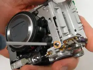
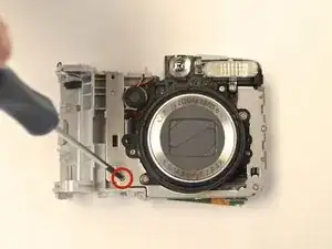
Unscrew the 3 mm Phillips screw head from the metal frame to begin detaching the battery housing unit.
-
-
-
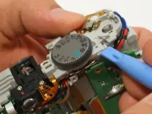
Use the plastic opening tool to separate the button circuit board from the shutter button and the settings dial housing unit.
-
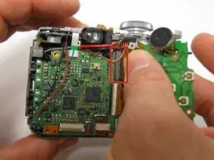
Carefully disconnect the ribbon cable that is attached to the user buttons circuit board away from the ZIF connector that is attached to the motherboard.
-
Remove the user button circuit board.
-
-
-
Use the spudger to remove the attached ribbon cable. Be sure to alternate the spudger on both sides of ribbon cable to remove evenly.
-
-
-
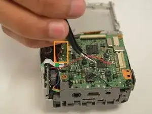
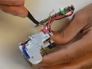
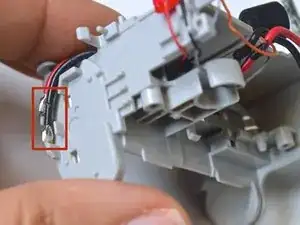
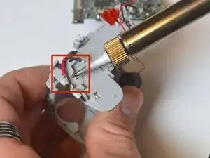
Desolder all of the wires attached to the motherboard and move them aside with the tweezers.
-
-
-
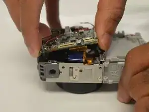
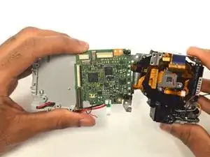
After disconnecting all ribbons, lift the motherboard to expose the ribbon cable connecting the motherboard to the lens.
-
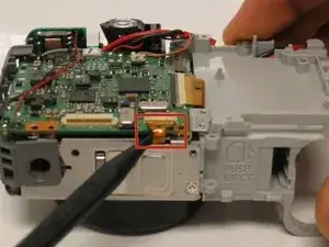
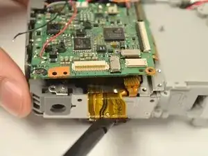
Use the spudger to remove the the ribbon cable attached to the motherboard. Be sure to alternate both sides of ribbon cable to evenly remove.
-
-
-
Turn the camera to the lens facing up. Remove the 3 mm Phillips head screw attached the bottom of the battery housing unit to the lens.
-
Turn the camera to expose the bottom. Remove the 30 mm Phillips head screw to disassemble the battery housing unit from the camera.
-
-
-
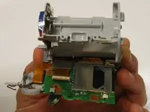
Remove the metal frame from battery housing unit.
-
Separate the lens from the motherboard. Put the lens housing unit aside for later use.
-
-
-
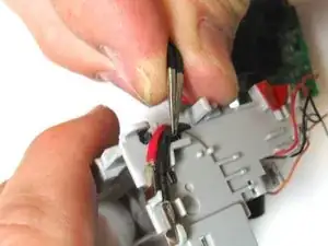
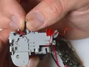
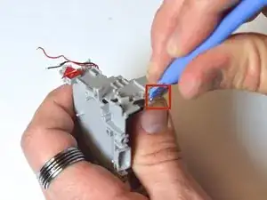
Use tweezers to remove the tape and rubber strap. Unravel the wires from the plastic hooks.
-
To reassemble your device, follow these instructions in reverse order.
