Einleitung

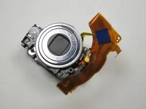
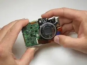
The lens is the device that focuses the image seen by a camera. Because it is the only moving part, it can easily malfunction, causing blurry pictures or even a camera error.

  1. O4N4YhNqefgppANR
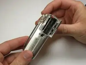
    • Remove the battery and SD card from the camera.

  2. RcfWZ4sVXCwdHkJw
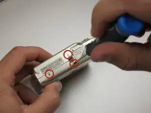
    • Remove the three 3.8 mm screws from the underside of the camera.

    • Each of the screws is slightly different, so it is important that you note the original location of each screw.

  3. mFXsf6DuNvpBvWSM
    mFXsf6DuNvpBvWSM
    LoWipxOowNgnjGpj
    2tPxL1WggNERhuyL
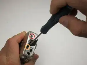
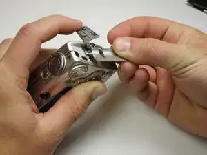
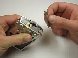
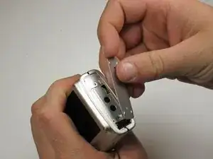
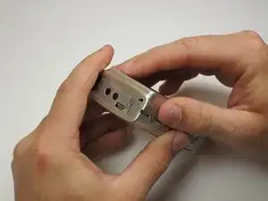
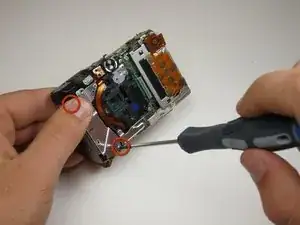
    • Remove the 3.2 mm screw from the right side of the camera.

    • Remove the 2.2 mm screw from the right side of the camera.

    • One of these screws is hidden under the USB port cover.

    • Lift the side panel off.

    • Remove the 1.8 mm screw from underneath the side panel.

  4. l5PQGGmVqpfpGrF2
    l5PQGGmVqpfpGrF2
    F3BUqEqHERjbmHGe
    BBC46DSkXE2chl5H
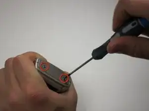
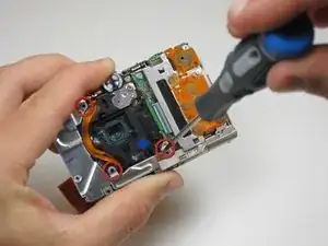
    • Remove the two 2.2 mm screws from the left side of the camera.

    • Lift the plate from the camera.

  5. XZbXPoKfJfmcOeKN
    XZbXPoKfJfmcOeKN
    ndlQK5QfmHAJGKjG
    MWWjUkluRo2cigTG
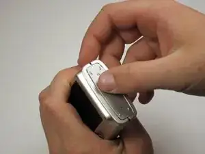
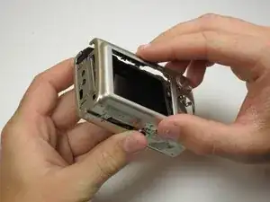
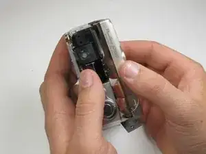
    • Gently lift the rear of the case to remove it from the camera.

  6. iTQeOPAORDIotnCN
    iTQeOPAORDIotnCN
    Wug1VjVVJPokWyJ2
    MFSQtIRSFMstdgF2
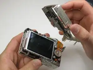
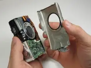
    • Remove the front of the camera body.

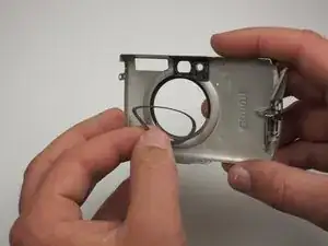
    • Be sure to keep track of the rubber ring.

    When removing the front, this little clear rubbery piece might fall out.

    Cody -
  7. YaLsNsnJRL1PE55j
    YaLsNsnJRL1PE55j
    pLbCiPRDaKBheMfg
    FhTkXiBxDhgbSiSh
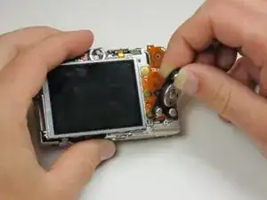
    • Peel the navigation buttons from the button panel and set them aside.

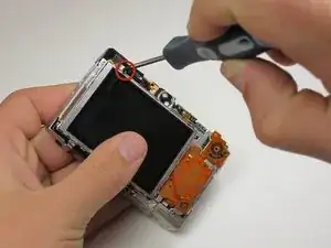
    • To free the LCD display, remove the 2.9 mm screw in the top left corner.

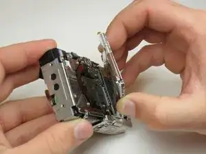
    • Rotate the screen clockwise until it lifts away from the camera.

    • There are two ribbon cables attached to the rear of the screen. Do not try to pull the screen off at this point.

    After removing the screw, there are two metal hooks overlapping. Once those are separated, it was easy to lift the display. Also, this metal bracket kept falling off.

    Cody -
  8. TgFtUSnFxYCFvCPN
    TgFtUSnFxYCFvCPN
    nZf31k4D1pTIKltO
    • To unplug the ribbon cables, pull them straight out of their plugs. Do this gently to avoid damaging the connections.

    • After disconnecting both cables, pull the screen away from the camera to remove it.

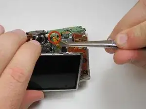
    During reassembly, I had to remove the button assembly to attach the large ribbon cable. I had to remove these two screws (there is a hidden ribbon cable under the button assembly, be careful)

    Cody -

  9. HF6eKBAypBkE4niL
    HF6eKBAypBkE4niL
    va1Xu1TDbLEEn2rT
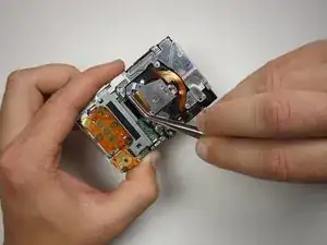
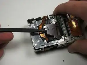
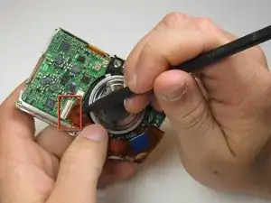
    • Now the photo sensor is exposed. In order to remove the ribbon cable from its port, first flip up the blue locking mechanism.

    • After the cable is unlocked, it easily pulls free.

  10. hMPTOQhtpJPhjFMU
    hMPTOQhtpJPhjFMU
    5KEvuEVDXsQBYnhr
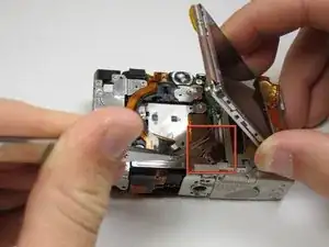
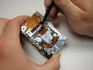
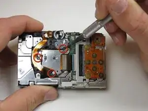
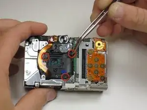
    • In order to remove the photo sensor, you will have to cut through glue and remove screws.

    • Use a knife to carefully slice through the glue at the tree points indicated. Try not to cut through anything but the glue to avoid damage.

    • WARNING: Knives are sharp. Treat them with respect.

    • Now remove the three .15 inch screws holding the photo sensor to the camera frame.

  11. 4F2CT2mksVk6AFq2
    4F2CT2mksVk6AFq2
    pdJVnOJZGHla5feQ
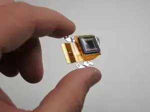
    • Now you can carefully lift up the image sensor and remove it from the camera.

    • Be careful not to lose the three small springs or the rubber grommet that lie beneath the sensor.

  12. 1QLJVv6VuVGB1lnb
    • You have now successfully removed the image sensor.

  13. PaIfeQcEJ2wQnsOv
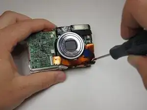
    • Once the image sensor is removed, turn the camera over and find the screw in the bottom right corner.

    • Remove this .01 inch screw to free the ribbon cables.

  14. 4oTJbdx3x4FjEQGJ
    4oTJbdx3x4FjEQGJ
    sWnPML4apRUrAs2N
    dPiqoZvIRvYvciAb
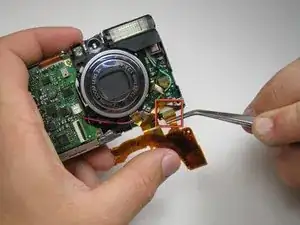
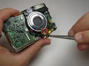
    • One by one, detach the three ribbon cables from their ports.

  15. SvQAufbInYXOFXa1
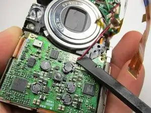
    • Pay special attention when removing this connector. It does not pull out like the rest of them. Instead, you must use a spudger to lift the connector vertically out of its slot.

  16. Bqihi1IVOBEuZXqd
    • Flip the camera over again so that the rear is showing and remove the two .065 inch screws holding the flash unit in place. They should be on the left side.

  17. VCHNRLxyhf1TVGS3
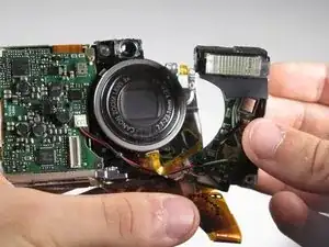
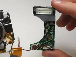
    • Now you should be able to remove the flash unit from the camera.

    • When removing the flash, be careful when handling the capacitor. It may contain a powerful charge. Discharge may result in damage and personal injury.

  18. YiZbfeSMZdAscmLL
    • You have now successfully removed the flash unit.

  19. EkEKotx3EsrCeCRu
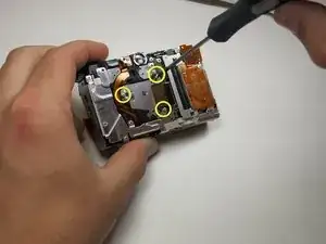
    • Next, remove the three .12 inch screws that hold the lens assembly to the camera.

  20. bZGIWd4P1croQtCU
    bZGIWd4P1croQtCU
    sRJDvXAHc2udt51B
    • Finally, pull the lens assembly away from the camera frame. Make sure that none of the ribbon cables are tangled up.

  21. g1TclsDITk4yYTEY
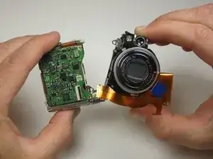
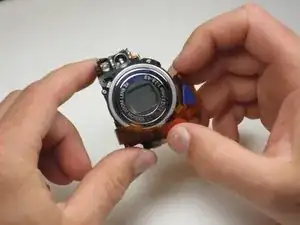
    • You have now successfully removed the Canon PowerShot SD550 Lens Assembly.

Abschluss

To reassemble your device, follow these instructions in reverse order.

Matthew Theiss

Mitglied seit: 14/04/11

149 Reputation

Ein Kommentar

hi. please help me to reassemble the lens completly.

thanks.

esmaeil -