Einleitung
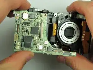
Follow this guide to learn how to replace the motherboard for the Canon PowerShot SD750. Prerequisites for this guide include disassembling the casing and removing the LCD screen.
Werkzeuge
-
-
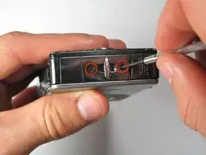
Turn the camera to the side that has the attachment for the wrist strap.
-
Unscrew the two black 3.4 mm screws with a #00 Phillips screwdriver.
-
-
-
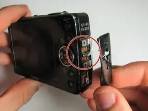
Remove the plastic subsection by prying it with your fingers.
-
The wrist strap attachment behind the subsection will come loose and may fall out.
-
-
-
Turn the camera over to the side opposite of the wrist strap.
-
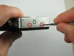
Remove the two silver 3.4 mm screws with a #00 Phillips screwdriver.
-
-
-
Flip the camera upside down.
-
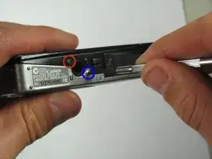
Remove the following screws with a #00 Phillips screwdriver.
-
One black 3.4 mm Phillips screw.
-
One silver 3.4 mm Phillips screw.
-
-
-
Place the camera on the side opposite of the wrist strap handle.
-
Then begin to pry the casing apart with both hands by applying pressure to the top and bottom of the camera.
-
Remove the small metal plate underneath the plastic covering and set aside. (It should be loosely attached)
-
-
-
Flip the camera right side up.
-
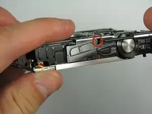
Remove the silver 3.5 mm screw (located on top of the camera) with a #00 Phillips screwdriver.
-
Grip the corner of the A/V digital port and pull up and outward.
-
-
-
Turn the camera forward so that the LCD screen is facing you.
-
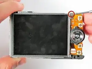
Remove the silver 3.4 mm screw at the top right hand corner of the LCD screen with a #00 Phillips screwdriver.
-
-
-
Slide the LCD screen to the left of the camera and then gently pull the LCD screen away from the camera.
-
Be sure to align the screen properly.
-
Be gentile and do not tear the ribbon connector for the LCD screen to camera.
-
-
-
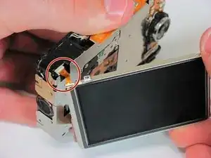
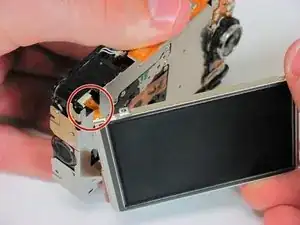
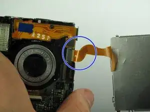
Locate the two ribbons connected to the camera and the LCD screen. (One is red and small and the other is wide and orange)
-
Remove the top left red ribbon by gripping the connector on the camera and sliding it straight out.
-
Remove the side orange ribbon by gripping the connector on the camera and sliding it straight out.
-
-
-
Place the camera forward so that the LCD screen side is facing up.
-
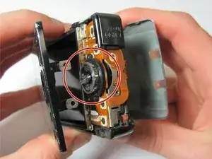
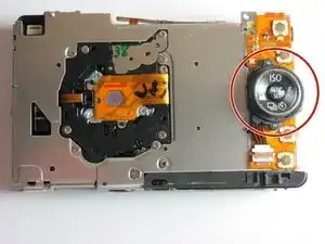
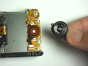
Remove the circular plastic button from the back of the camera.
-
-
-
Leave the camera facing forward.
-
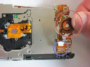
Grab the round orange and black stripped connector as pictured.
-
Then rotate the connector upward and pull the ribbon out.
-
-
-
Place the camera backward so that the lens is facing up.
-
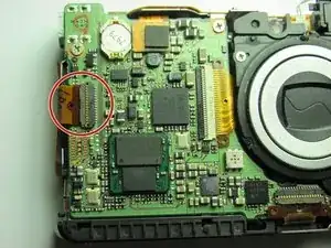
Disconnect the ribbon that attaches to the motherboard by rotating the connector upwards.
-
Pull the ribbon out of the ZIF connector.
-
-
-
Stand the camera upward.
-
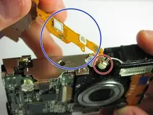
Disconnect the white connector attached to the flash by pulling it out on the top right side of the camera.
-
Then remove the orange circuitry.
-
-
-
Place the camera backward so that the lens is facing up.
-
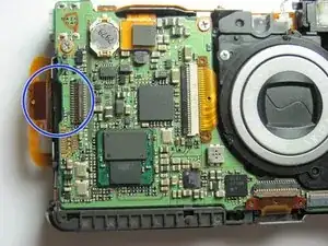
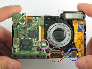
Disconnect the ribbon at the bottom of the main board by flipping up the brown ZIF connector and sliding the ribbon out.
-
Remove the right most square connector at the bottom of the camera by flipping up the connector with two fingers until it detaches.
-
Locate and remove the white rubber cover on the microphone.
-
-
-
Leave the camera facing backward so that the lens is facing up.
-
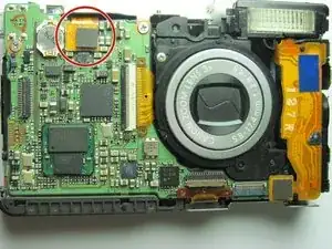
Remove the square connector at the top of the motherboard by grabbing the connector with two fingers and pulling up until it detaches.
-
Refer to the picture for correct removal.
-
-
-
Leave the camera facing backward so that the lens is facing up.
-
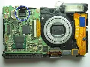
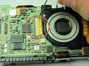
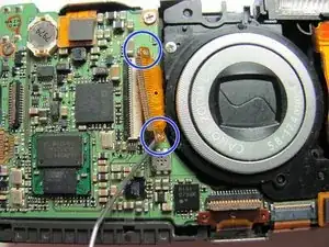
Flip up the ZIF locking mechanism using a paperclip
-
Use the paperclip to pull the ribbon cable from the ZIF socket.
-
-
-
Leave the camera facing backward so that the lens is facing up.
-
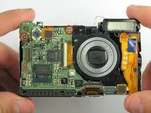
Remove the two flat silver 3.46 mm Phillips screws with a #00 Phillips screwdriver connecting the motherboard to the frame of the camera.
-
-
-
Leave the camera facing backward so that the lens is facing up.
-
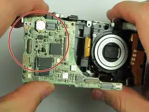
Pull the motherboard out by lifting it up on the left side about a 1/2 inch from the case and then slide it to the left.
-
To reassemble your device, follow these instructions in reverse order.
