Einleitung
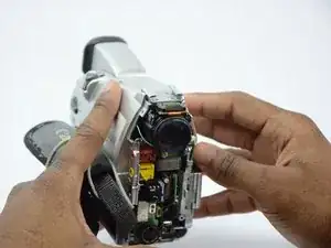
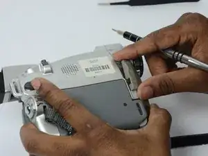
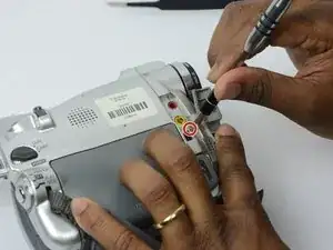
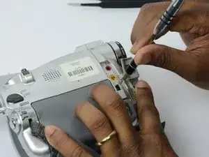
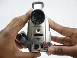
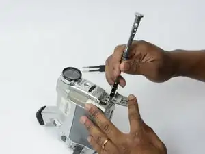
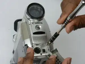
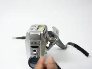
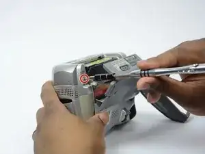
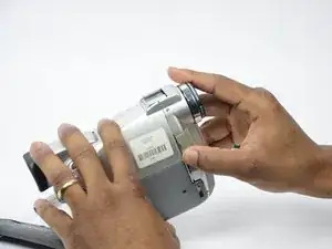
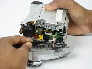
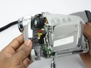
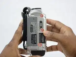
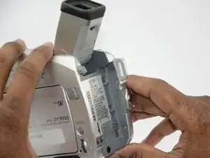
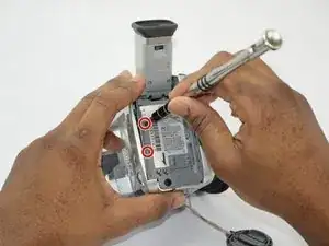
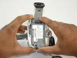
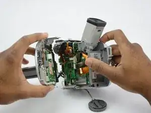
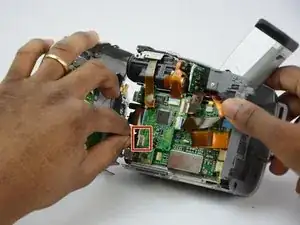
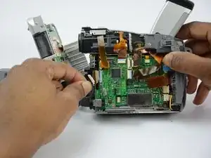
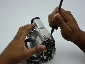
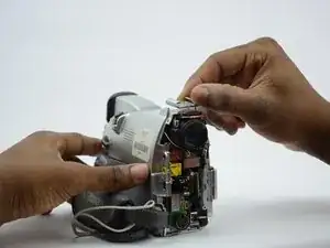
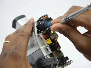
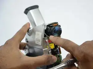
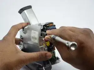
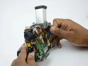
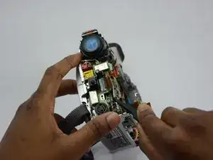
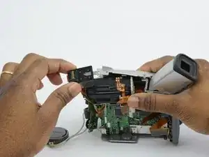
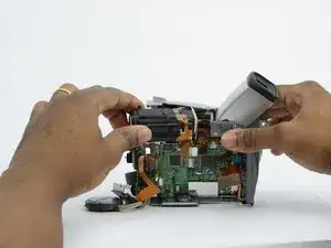
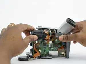
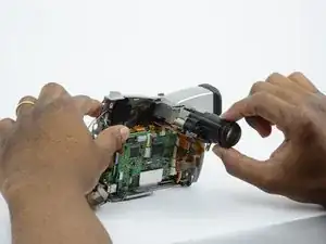
The lens of the Canon ZR70MC is the most difficult component to replace. There are many steps in this guide so make sure that you allow yourself adequate time to complete this replacement guide. There are also many small parts so make sure to have a designated area to keep the parts that you take off. This guide will show you how to gain access to and replace the lens of the camcorder. Do not damage any films or wire that you come across.
Werkzeuge
-
-
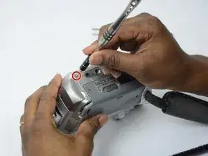
Turn the ZR70MC so that you can see the bottom of the camcorder.
-
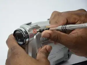
Unscrew the 3.35 mm located in the top left portion of the camera.
-
-
-
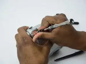
Turn the camera on the side and remove the cover for the audio inputs. There is a 2.65 mm screw located behind the cover.
-
Remove the 2.65 mm screw.
-
-
-
Remove the cover located on the front of the camcorder and remove the cover by pulling on the bottom groove.
-
Locate and remove the two 3.35 mm screws.
-
-
-
Turn the camcorder so that the bottom is facing up and open the tape cassette compartment.
-
There is one 3.35 mm screw located under the tape cassette panel on the front left side of the camcorder. Remove the screw.
-
-
-
Now that all of the screws are removed, remove the front panel by gently pulling on the front panel.
-
-
-
Use tweezers to gently pull the speaker wire from the main body of the camcorder.
-
Pull the front panel completely away from the main body of the camcorder.
-
-
-
Turn the camcorder so that the back is facing you.
-
Remove the 3.75 mm screws from the back of the camcorder that hold the side panel in place.
-
-
-
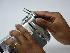
Gently pull the two black wires from their connections. These black wires are the only thing left connecting the side panel to the main body of the camcorder.
-
-
-
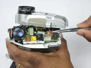
Gently pull the orange films out of their connections. This will allow you access to all components of the main body.
-
-
-
Locate the four 3.5 mm screws on the top of the camcorder that holds the lens in place.
-
Remove the four 3.5 mm screws.
-
Remove the metal plate that the screws were holding down.
-
-
-
Remove the first 2.75 mm screw that holds the lens in place.
-
The second 2.75 mm screw that holds the lens n place is difficult to see. If you look directly into the "hole" beside the lens you will see the 2.75 mm screw.
-
Remove the second 2.75 mm screw.
-
-
-
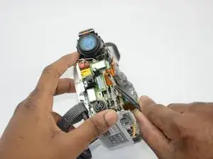
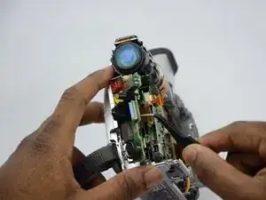
Turn the camera so that you can see the orange film that needs to be pulled away.
-
Use tweezers to gently pull the orange film away from the connection.
-
-
-
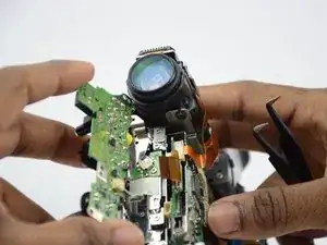
Use the tweezers to pull the green circuit board away from the main body of the camcorder.
-
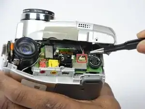
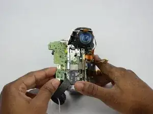
Pull out the white wire from its connection so that the green circuit board can be completely removed form the main body of the camcorder.
-
Removing this green circuit board allows access to the camcorder lens.
-
To reassemble your device, follow these instructions in reverse order.
