Einleitung
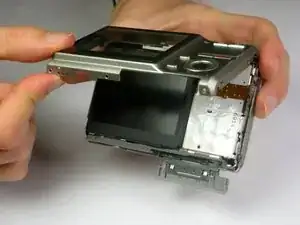
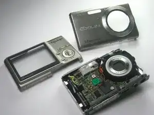
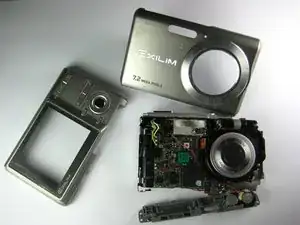
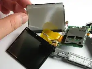
If the LCD screen has cracked, stopped working, or malfunctioned in any other way, you will need to replace the screen. This guide will break down the camera all the way to having a separate LCD screen from the camera. Follow the guide in reverse in order to install the new LCD screen.
Werkzeuge
-
-
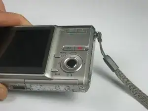
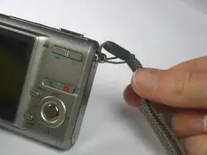
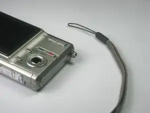
Remove the strap from the camera by pulling the thin cord out, creating a small loop, then pushing the thicker cord back through this loop.
-
-
-
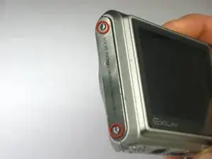
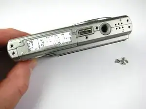
Remove the two Phillips screws (2.83 mm) from the left side panel of the camera casing.
-
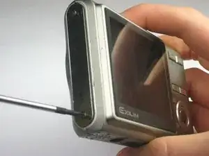
The left panel can now be removed. However, one piece of tape attaches it to the camera, so a spudger may be required to ease the panels off.
-
Repeat for the right side panel of the camera.
-
-
-
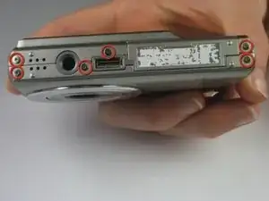
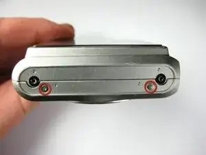
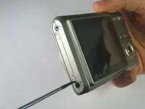
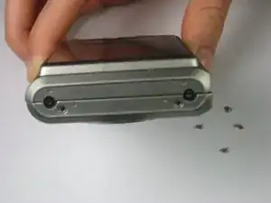
Remove the two Phillips screws (2.79 mm) on the left side of the camera where the metal panel used to be.
-
Repeat for the two Phillips screws (2.79 mm) right side of the camera.
-
-
-
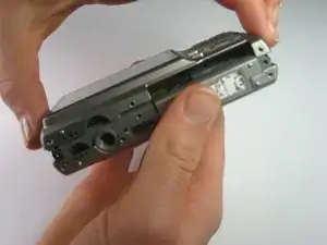
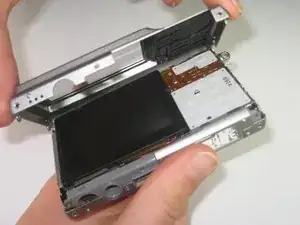
With the LCD screen facing up towards you, start at the bottom of the camera and gently pull off the back of the casing.
-
-
-
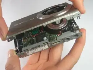
With the front side (with the lens) facing up towards you, start at the bottom of the camera and gently pull off the front of the casing.
-
-
-
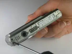
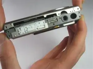
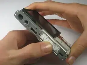
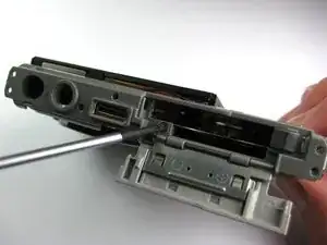
Look at the bottom of the camera. Take out the Phillips screw (1.77 mm) holding on the bottom plastic piece.
-
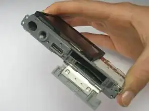
The bottom plastic piece is held on to the main frame of the camera only by two thin wires.
-
-
-
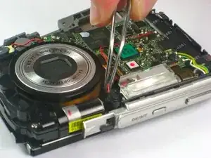
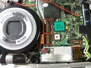
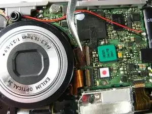
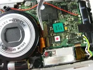
Using tweezers or your finger nails, pull up the brown flaps where the three orange film strips meet the circuit board.
-
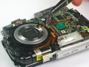
Use the tweezers to pull all three orange film strips out of each port. The strips should come out easily.
-
-
-
Flip the camera over to the side with the LCD screen.
-
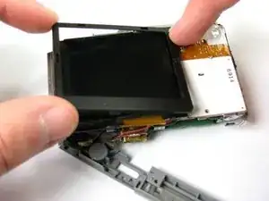
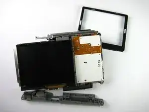
Gently remove the plastic cover that borders the LCD screen starting with the top left corner, then the bottom left corner, and finally the bottom and top right corners.
-
-
-
Turn the camera back to the front side, with the lens facing up and the LCD facing down.
-
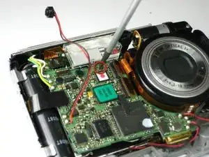
Remove the Phillips screw (3.30 mm) located below the flash on the circuit board.
-
-
-
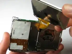
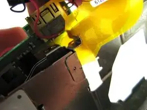
Slide the gold strip that connects the LCD screen to the circuit board through the small gap at the bottom of the camera.
-
-
-
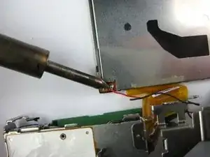
Using a soldering station and solder wick or other solder removing instrument, remove the solder holding the two wires of the LCD screen to the circuit board.
-
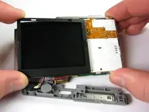
You have now completely removed your LCD screen. It can now be replaced or cleaned.
-
To reassemble your device, follow these instructions in reverse order.
