Einleitung

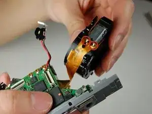
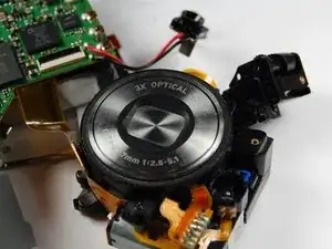
This guide shows you how to remove the zoom lens from the camera.

  1. jUMfAI2sqNmIW2RR
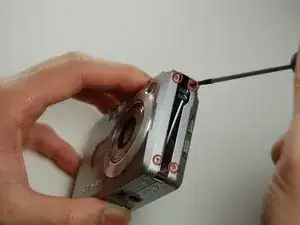
    • Remove the four screws on the side with the speaker

  2. rIo5t2fUfCG6TUIb
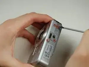
    • Remove the four screws from the bottom of the camera.

    • Note: Bottom screws are longer than the top ones, so label accordingly for easy reassembly

  3. rffpefVP4SZdtgLQ
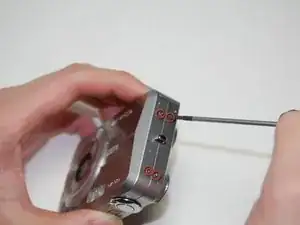
    • Remove the four screws on the side opposite of the speaker.

  4. 2qRWJXuxZdaHHDOW
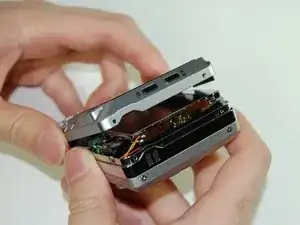
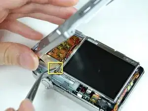
    • Once all screws have been removed, gently pry open bottom casing.

    • With tweezers, carefully remove ribbon from LCD screen.

    • Set bottom casing aside.

  5. uaCQZLZWAbuUgTHH
    uaCQZLZWAbuUgTHH
    dI5I2QsUsxaM45FD
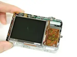
    • Remove ribbon from the rear casing.

    • Set aside rear casing.

  6. kj2g3WIitnTXDN55
    kj2g3WIitnTXDN55
    dfKlBFGUl66WVb4M
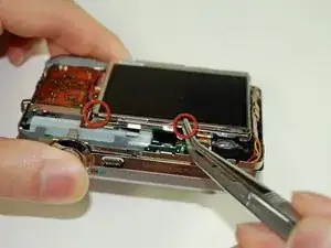
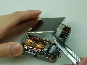
    • Use tweezers or prongs to pry the LCD screen off from the opening.

    • Note: the bottom of the LCD screen is attached to the frame by a few pieces of black tape.

  7. 3BH2KAslaSRghGZk
    3BH2KAslaSRghGZk
    KXrSUqG5q4U322nR
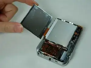
    • Lift up the LCD screen, slowly move it to the other side.

  8. XtGnLnsriWgKQLbL
    XtGnLnsriWgKQLbL
    GZd1wYDKlJY36X24
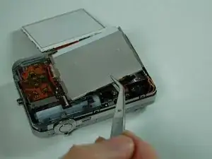
    • Pry off the LCD casing which is taped on to the frame.

  9. NQDhxqDZMeXlFcIY
    NQDhxqDZMeXlFcIY
    FgL1AvqtvMEVHqeU
    qnXgEIV1MxucQQEQ
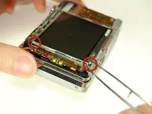
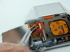
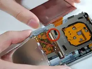
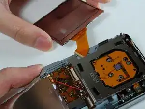
    • Flip open the connector holding the ribbon.

    • Pull out the LCD screen with the ribbon from the camera.

  10. 2QZfjTbZSJebd5s4
    2QZfjTbZSJebd5s4
    cXCKEcKuG6pqnxbw
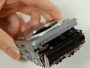
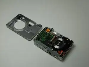
    • Pull apart the front casing.

  11. Inns5jOEB6DfnXdo
    Inns5jOEB6DfnXdo
    rpDLKOLSeaVyYEXY
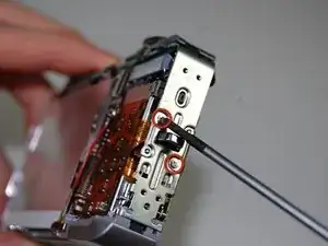
    • Remove two screws on the side where the battery is located.

    • Remove the lanyard loop after the screws come off.

    • Slowly pull the side casing so it becomes dislocated from the top of the camera frame.

  12. WStxgCSv6hLpGnSL
    WStxgCSv6hLpGnSL
    mAZV1sNeDGYwcqAV
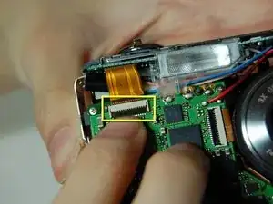
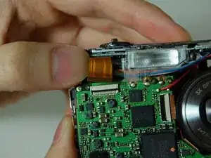
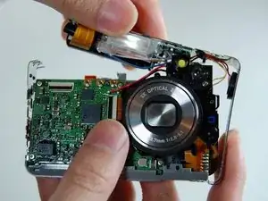
    • On the front of the camera near the flash flip the connector holding the ribbon.

    • Remove the ribbon from the connector.

  13. npqns4hZkxQQYYCi
    npqns4hZkxQQYYCi
    LPBwUIZCvB2F3KYR
    IidoddHEISNDeNcC
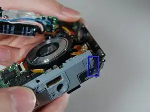
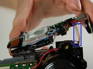
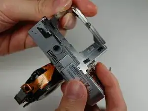
    • Carefully remove the L shaped frame from the camera.

    • At the bottom of the camera the L shaped frame is being held in by two plastic bumps and a metal tab. Pop the frame off the bumps and tabs.

    • Note: There is a yellow and orange wire soldered onto the camera. Be careful not to pull them off.

    • The blue box is the speaker box.

  14. SJQlHEPvhy4skV1Q
    SJQlHEPvhy4skV1Q
    p1tJnLySWNu3YD4t
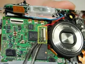
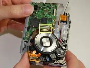
    • On the logic board next to the lens is a connector with a ribbon.

    • Flip the connector and remove the ribbon

  15. pHHEnOgFgtaNSQ2Q
    pHHEnOgFgtaNSQ2Q
    dJ5lAweAvuxeicFn
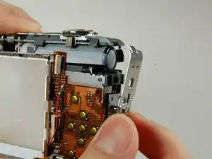
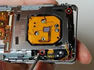
    • Remove the frame on the back side of the camera where the LCD screen was.

    • Remove the two screws connecting the frame with the camera

    • Slowly pry off the frame from the camera

    • After removing the frame a plastic piece with two yellow button connections should fall off.

    • Note: This plastic piece is soldered to two wires a yellow and orange one.

  16. NHAvBPVPy3kkur6x
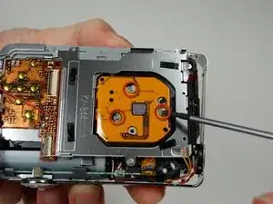
    • On the back of the camera where the LCD screen was, remove 3 screws located behind the lens.

  17. VbtxALNWfOAKyniH
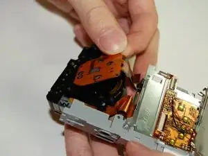
    • Remove the large orange ribbon previously held in by screws from the camera.

  18. VsZB3jJV2DDuhvDg
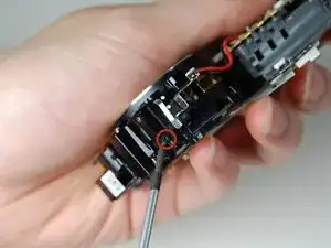
    • On the backside of the camera where the indicator lamp is located remove the two screws.

  19. KiJ4IPLFKmHRstWv
    KiJ4IPLFKmHRstWv
    VK2XCSV23fHw2glG
    SwqLI6BcpsLqkCnH
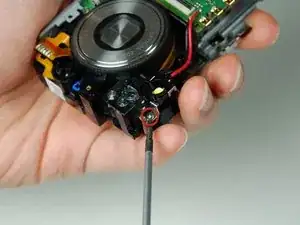
    • On the side of the indicator lamp remove a screw.

    • On the front side of the indicator lamp remove the a screw.

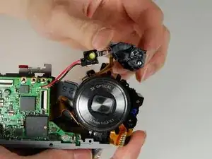
    • This should remove the indicator lamp from the lens.

  20. I3N1iowpACPsNF4H
    I3N1iowpACPsNF4H
    gXYZax12lBTGOghQ
    • The lens is now detached from the camera except for the ribbon soldered onto the logic board.

Abschluss

To reassemble your device, follow these instructions in reverse order.
Ray

Mitglied seit: 26/01/11

219 Reputation

0 Kommentare