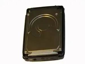
Einleitung

  1. XQJaWKtAcGEObWkZ
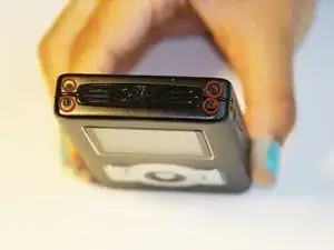
    • Using a Phillips #00 screwdriver, remove the four 1.1mm long screws from the top side.

  2. VVfcJHSIa2lEDckt
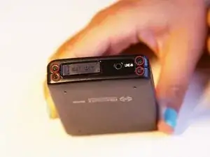
    • Using a Phillips #00 screwdriver, remove the four 1.1mm long screws from the bottom side.

    • Remove the warranty sticker across the bottom.

  3. c2J6YKqA5AyPfD2j
    c2J6YKqA5AyPfD2j
    hIpIlRajTjYxrHXq
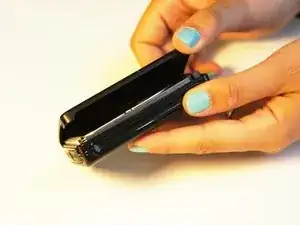
    • Gently lift off the back and front casing.

    • The outer shell should easily come apart.

  4. iCMcNOZh6yqEerPD
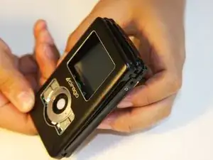
    • Make sure the device screen is face down.

  5. CYoyhOlAe2IfMKHF
    CYoyhOlAe2IfMKHF
    FgcY22qilVQAfdAc
    PU4FBAPPj3DhFUtA
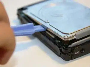
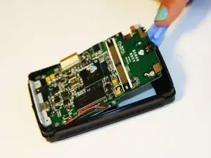
    • Using the plastic opening tool, wedge the tool underneath the bottom left edge of the hard drive.

    • Raise the bottom edge of the hard drive 15 degrees up from the device.

  6. hP5i55XQOowISIHF
    hP5i55XQOowISIHF
    UUFWrNf2HkLmS1ro
    q2GSdUcTETUUeV1o
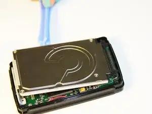
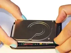
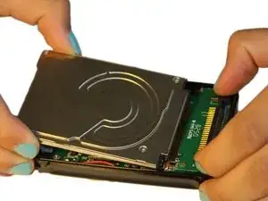
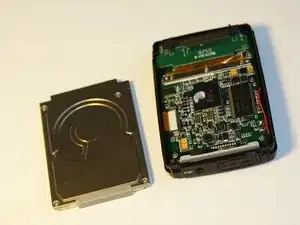
    • Place fingers on the IDE connectors and gently slide the hard drive out from the IDE module.

  7. V2N4UnQ4BTyDZdPV
    V2N4UnQ4BTyDZdPV
    5o3QGZLHJIaI2hhq
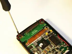
    • Using the Phillips #00 screwdriver, unscrew the two 1.5mm long screws holding the IDE connector to the motherboard.

  8. NCOANUFRYcFUAdxy
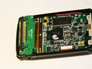
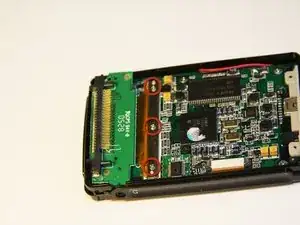
    • Using the Phillips #00 screwdriver, unscrew the three 1.5mm long screws on the metal bracket.

  9. 4GOs1FCXFEuPmQxm
    4GOs1FCXFEuPmQxm
    Ptbfla36MPXCHdgv
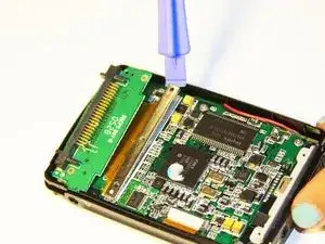
    • Using the plastic opening tool, completely lift the metal bracket off of the motherboard.

    • Using the plastic opening tool, completely lift the rubber insulator off of the motherboard.

  10. hJUeXAH2bRYheTbM
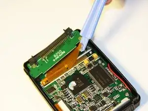
    • Using the plastic opening tool, completely lift the ribbon off of the motherboard.

  11. 16Fe4pDuwsCRM32a
    16Fe4pDuwsCRM32a
    YKjg13tsOjxueR2p
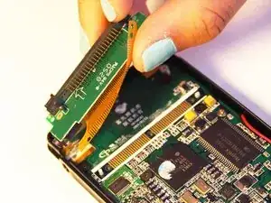
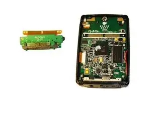
    • Completely remove the IDE connector from the device.

    • The audio jack is attached to the IDE connector. Pull at a 45 degree angle from the audio jack.

  12. yxbXLLnQTGa4hlk2
    yxbXLLnQTGa4hlk2
    MXjmDZTZNHZqmEFB
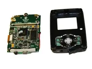
    • Using the plastic opening tool, wedge the tool underneath the top edge of the motherboard.

    • Completely remove the motherboard.

    • The motherboard should slide out easily.

  13. cRCBmDSAyBdwHrHP
    • Set aside the front cover.

    • Flip over the motherboard.

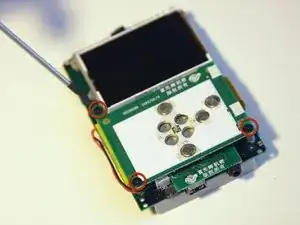
    • Using the Philips #00 screwdriver, remove the three 4mm long screws holding down the button module.

  14. mGuOcSyXX3RdWeAW
    mGuOcSyXX3RdWeAW
    gGB22TfGMOADqjuF
    sqELHyLTxuEyNRKB
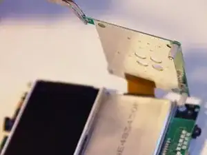
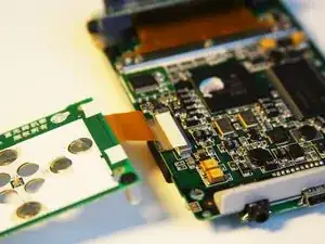
    • Using the tweezers, lift up the button module to a 180 degree angle.

    • Leave the button module attached by the ribbon.

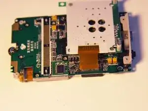
    • Flip over the motherboard with the button module still attached.

  15. VtgfH6C2kIk3KN5A
    VtgfH6C2kIk3KN5A
    3Af3UKGU32vaD5o6
    11u1YWC3SIGDuJPd
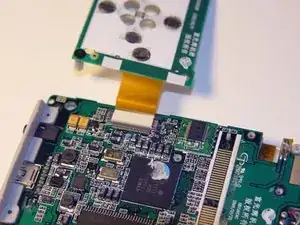
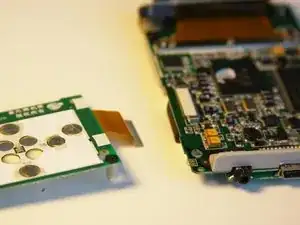
    • Fold the button module over the motherboard.

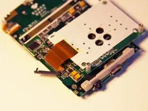
    • Using the tweezers, remove the ribbon pin.

    • The ribbon pin should snap completely off of the motherboard.

  16. K21dKSxDE1p4yoST
    K21dKSxDE1p4yoST
    VhsreSXDg24Lijr4
    • The ribbon should easily detach from the motherboard.

  17. 45GJKI1jqJXEIKp6
    45GJKI1jqJXEIKp6
    W1llYAWGEfHoMe11
    • Flip over the motherboard so the screen faces up.

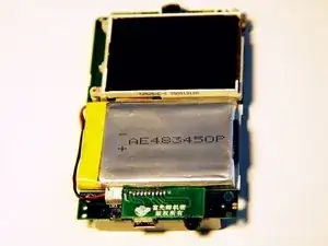
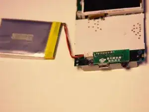
    • Carefully slide the battery off of the motherboard.

    • Leave the battery cable connected to the motherboard.

  18. XSEiCgrJKhPvfKWo
    XSEiCgrJKhPvfKWo
    MQZfxu2J4DFdWJv2
    PDo211CACOW3ndfA
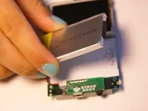
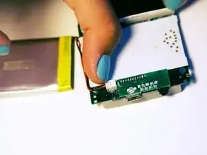
    • Place two fingers on the battery connectors and gently pull the power cable connector completely out from the motherboard.

    • Do not pull directly on the wire as it may damage the connector.

Abschluss

To reassemble your device, follow these instructions in reverse order.
Ryan Sutardji

Mitglied seit: 29/06/12

171 Reputation

0 Kommentare