Einleitung
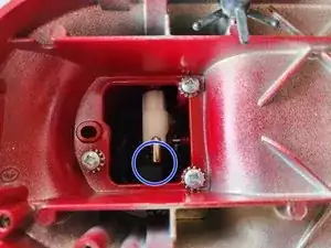
While rare, being the only plastic piece in the bowl-lift mechanism, occasionally the internal bowl-lift adjustment bracket can fail. This can cause the bowl-lift arm to either no longer function or cause the bowl to not raise/lock into its proper position. This guide takes you step-by-step through replacing the incorrectly functioning part.
NOTE: This part is not responsible for setting the final/locked height of the bowl. That is the responsibility of the Bowl-Lift Arm Adjustment Cam. So if your bowl is raising too high or just barely too low, look into replacing that part instead.
Werkzeuge
Ersatzteile
-
-
Place a couple dish towels or other soft materials on the base to protect it from any potential impact.
-
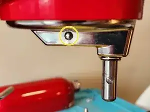
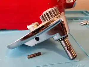
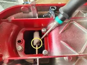
Disconnect the planetary from the motor drive shaft by removing the retaining pin (circled in yellow). You can do this with a hammer and either a pin punch or a Torx T15 screwdriver. Simply hammer the punch/screwdriver on the pin until it comes out the other side.
-
If the planetary assembly doesn't fall out, you might have to give it a firm pull straight down to remove it.
-
-
-
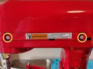
Using a #2 Philips Screwdriver, remove the screw which holds on the trim band.
-
Remove the trim band.
-
-
-
Remove the four screws (circled in yellow, two on each side) using a #2 Philips Screwdriver
-
Remove the motor housing by lifting it straight up.
-
-
-
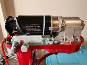
There are two motor support brackets: one in front, one back (shown in the first image)
-
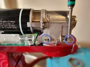
Each bracket is attached to the motor by two screws (one on each side).
-
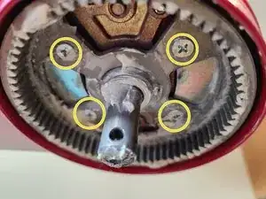
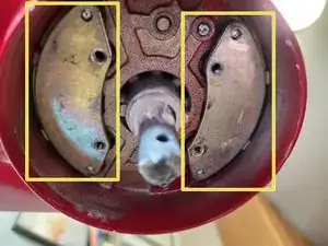
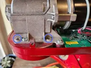
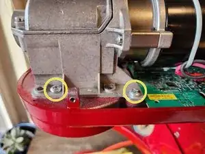
Using a #2 Phillips screwdriver, remove the four screws (circled in yellow in the second and third images) which attach the two motor support brackets.
-
-
-
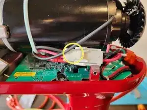
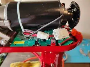
Disconnect the motor power cable by depressing the locking tab (circled in yellow) while pulling the connector apart.
-
-
-
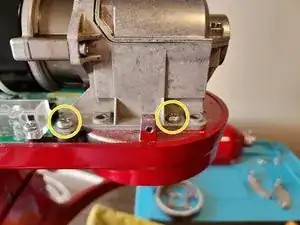
Using a #2 Philips screwdriver, remove the four screws (indicated in yellow, two on each side) attaching the powertrain/motor to the mixer body.
-
-
-
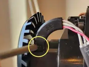
Remove the hall effect sensor from its mount by pressing down on the tab indicated in the first image and sliding it out.
-
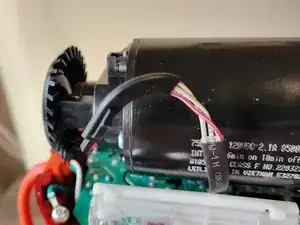
Now that the powertrain/motor is fully disconnected from the mixer, remove it and place it to the side.
-
-
-
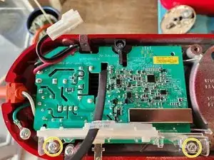
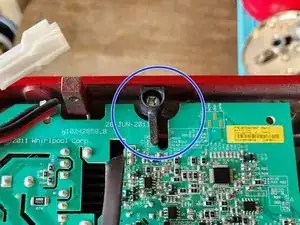
Using a #2 Phillips screwdriver, remove the two screws (circled in yellow in the first image) holding down the speed/motor control assembly.
-
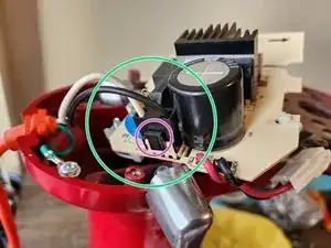
Slide the board over slightly to to allow the black support at the top of the board (circled in blue in the second image) to slide through the notch in the board or remove the support with a #2 Phillips Screwdriver.
-
Flip the board over to access the power connector (circled in green in the third image).
-
Remove the power connector by depressing the tab on the edge of the connector (circled in purple in the third image) and pulling upwards.
-
The speed/motor control assembly can now be removed and placed to the side.
-
-
-
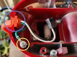
Using a #2 Philips screwdriver, remove the screw (circled in yellow) which attaches the ground wire to the mixer body.
-
Remove the power cord by lifting up at the strain relief where it passes into the mixer (circled in blue).
-
-
-
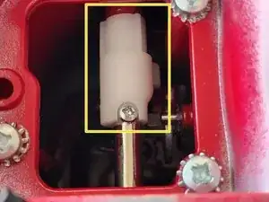
Using a #1 Phillips Screwdriver, remove the small screw anchoring the Bowl-Lift Arm Adjusting Bracket to the handle.
-
Slide the handle out from the mixer body, as shown in the second picture. Continue sliding the handle out until the Bowl-Lift Arm Adjusting Bracket comes free.
-
Using needle nose pliers, detach the C-clip holding the Bowl-Lift Arm Adjusting Bracket from the Bowl-Lift Rod (circled in green). Then remove the Bowl-Lift Arm Adjusting Bracket by sliding it off the Bowl-Lift Rod (slide it towards the direction of the handle).
-
To reassemble your device, follow these instructions in reverse order.
If you have difficulty accessing the screw hole for the Bowl-Lift Arm Adjusting Bracket, insert the handle fully into position and rotate the handle until the screw hole aligns with the notch in the Bowl-Lift Arm Adjusting Bracket
