Einleitung

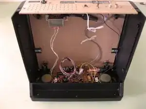
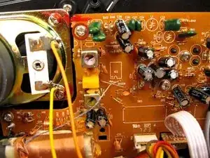
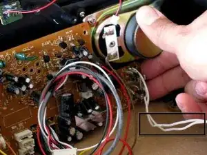
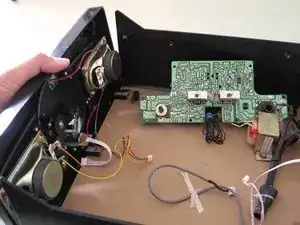
We all love to rock out with our vinyl out. Regardless of our age, though, sometimes the music is too loud and we blow our speakers.

Make sure you unplug your radio before starting!

  1. vpEqm6JGOWwqj61v
    vpEqm6JGOWwqj61v
    wQVDRUKACIo3MmpW
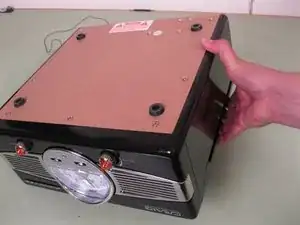
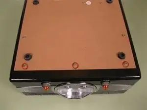
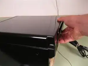
    • Turn the radio upside down, being careful to hold the turntable's lid.

    • Remove the three 6 mm screws on the bottom near the front of the radio.

  2. SCkPTSGYYP1DWYNa
    SCkPTSGYYP1DWYNa
    kEOdN2Lo2R4TMTlZ
    • Turn the radio right side up.

    • Remember to hold the turntable's lid while flipping the radio.

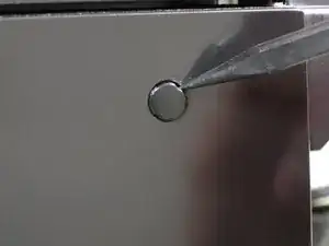
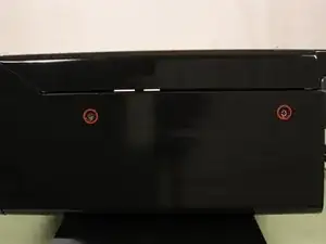
    • Using a spudger, remove the plastic screw covers on both side.

    • Remove the two 8 mm screws on each side of the radio.

  3. DUdnNrbEZsi1tEP5
    DUdnNrbEZsi1tEP5
    IZ51MBVKCL1eCfYo
    TQkMGDqQuKAGBElW
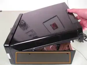
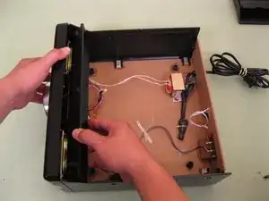
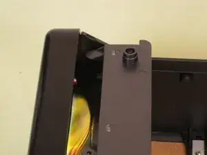
    • Gently pull up on the back of the turntable while pulling back.

    • Do not lift up too high. There are cables inside attached to the turntable.

    • Place the entire radio on its right side and lower the turntable. The orange box indicates which side is the right side.

  4. LqEMYRLZKDo2cqnb
    LqEMYRLZKDo2cqnb
    Kid1JEhy3qfKp6ao
    fCGtvkYpaEWFBZhy
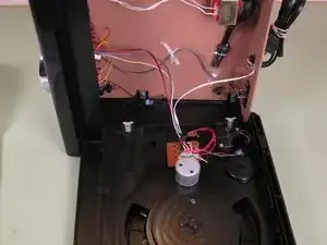
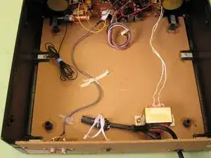
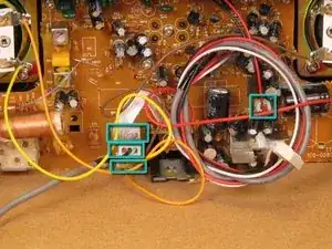
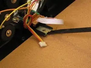
    • Unwind the black strap wrapped around the cables connected to the turntable.

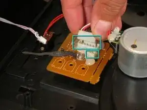
    • Remove the two plastic connectors attached to the circuit board on the turntable.

    • The plastic connectors are called Molex connectors.

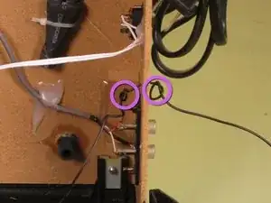
    • Untie the two knots keeping the antenna cable in place and pull the cable into the radio's body.

  5. XgfMtHefg2RdrGSJ
    • Now's a good time to coil the cables you've disconnected. This will help keep them out of the way when working on the rest of the radio.

  6. EglYbWbvEkj4oppF
    EglYbWbvEkj4oppF
    EfieOK1rGeUQLgc1
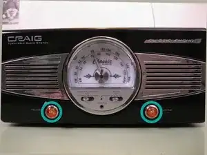
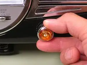
    • With the power of Greyskull, firmly grab the knobs with your thumb and forefinger and pull them out.

  7. VCcniDAttPvXKPxo
    VCcniDAttPvXKPxo
    5OvCwTJ5wutYTSZF
    eUfFLnvMMhGuVpMy
    • Place the radio with the front facing down and the top of the radio facing you.

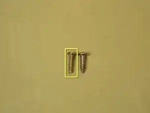
    • Remove the seven 6 mm screws holding the cross member in place.

    • The screw called out in yellow is slightly different than the other screws. The length is the same but it has a tighter thread pitch. Make sure it goes back in the same place.

  8. Nc26sJJTRgLNbAM2
    Nc26sJJTRgLNbAM2
    hEeeQ3qvmyljfNI6
    • Place the radio right side up and face it to your left.

    • With a firm grip, pull the top of the radio's face away from the body. Using you other hand, rotate the cross member clockwise 90 degrees.

    • Once the cross member is free, you can lift it out of place.

  9. 2BQj1DR4XjfbRyqs
    2BQj1DR4XjfbRyqs
    fGHAgi2pnp2rpgDd
    YEDZlnPwd4fAAyEk
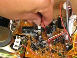
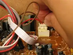
    • Remove the four Molex connectors for the speakers, headphone jack, line out and light.

  10. ZhRwFiiDlZLHaJSZ
    ZhRwFiiDlZLHaJSZ
    utHuHRMxCXEVUlaX
    LjJcqy1LZhbdKHAR
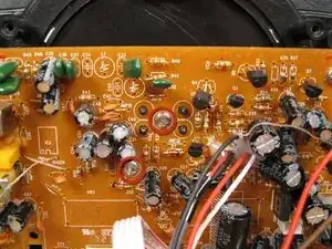
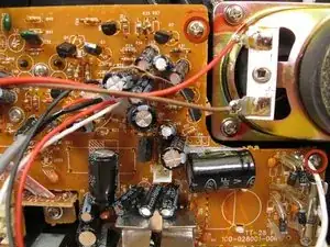
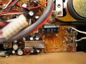
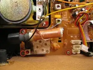
    • It is difficult to see all of the circuit board's screws from one angle. This series of photos starts at the top center and moves clockwise around the circuit board.

    • Screws are only called out when they make their first unobstructed appearance.

    • The screw in the black square is not part of the main circuit board and should not be removed.

    • Remove the ten 4 mm screws holding the circuit board in place.

  11. NK3mxhL1sMsfgcrA
    NK3mxhL1sMsfgcrA
    UknwDAwOOImjXXI6
    4fXZmLbTuxIADbZU
    • Continue removing the circuit board's screws.

    • On both sides place two fingers between the circuit board and the face of the radio.

    • Gently pull the circuit board straight back being careful not to break the volume and tuning knob posts on the opposite side of the board.

    • The two white cables are soldered to the circuit board and the power transformer at the back of the radio. Once removed, the circuit board has to be set aside inside the radio.

  12. rxtT2CnsFHD3hAo5
    rxtT2CnsFHD3hAo5
    QWL4CTNC1SsxXcO1
    • With the flat end of a spudger, scrape away the glue between the mounting tabs and the bottom of the radio.

    • Gently pull the face of the radio away.

  13. HUCxo3V1YJrXJ2h3
    HUCxo3V1YJrXJ2h3
    ImvDyoYM5dcyU6r5
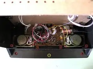
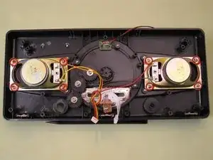
    • Well you've finally made it to your destination. Remove the eight 6 mm screws holding the speakers in place.

    • The speakers are not glued in, but you might have to use a little extra force to remove them.

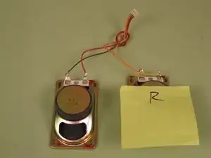
    • It's also a good idea to label your speakers so you put them back in the correct side.

Abschluss

To reassemble your device, follow these instructions in reverse order.
Eric Flores

Mitglied seit: 01/08/12

128 Reputation

0 Kommentare