Einleitung
Use this guide to disassemble your drill for cleaning, troubleshooting, or other maintenance.
Werkzeuge
-
-
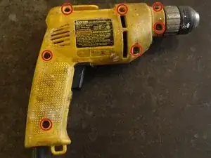
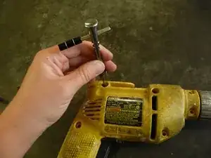
Remove the seven T20 screws.
-
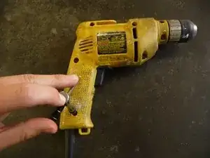
Use the T-handle configuration of the screwdriver for the necessary force to loosen the screws.
-
-
-
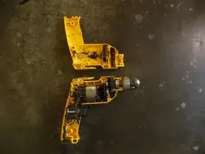
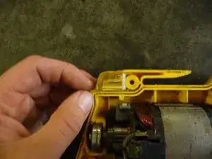
Wiggle the power supply cord to loosen the clamshell set and rotate the case open.
-
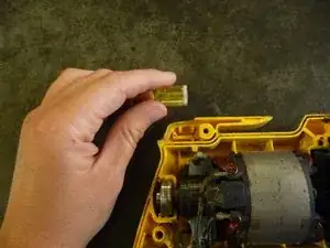
Remove the bubble level.
-
-
-
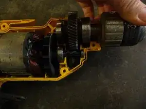
Disengage and remove the spindle and gear assembly.
-
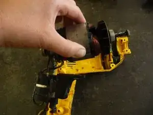
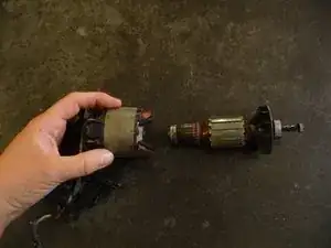
Lift out the field assembly and armature.
-
-
-
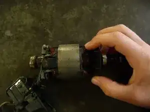
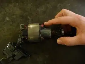
Slide the armature out of the field assembly.
-
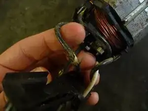
Rotate the field assembly to lay on the top. This allows for easier access to the frayed wire.
-
-
-
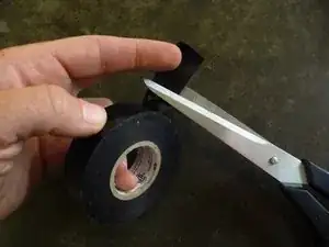
Cut a piece of electrical tape about one inch long.
-
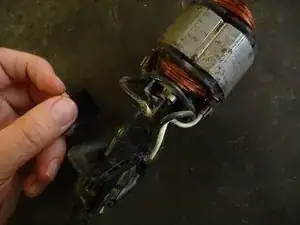
Wrap it tightly around the frayed section of the wiring.
-
-
-
Lay the field assembly back down and align the armature.
-
Reinsert the armature and rotate to point it "drill downward."
-
-
-
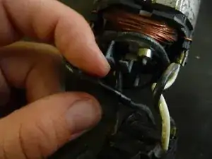
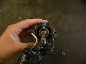
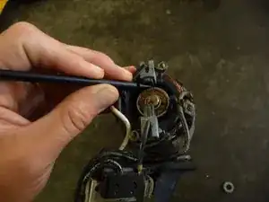
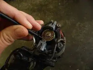
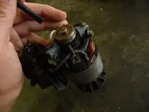
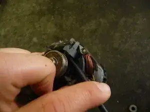
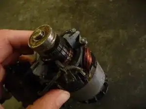
Compress the brushes in the brush ring so the ball bearing at the end of the armature assembly can get through.
-
Use a spudger or similar thin tool.
-
-
-
Lay the field/armature assembly down.
-
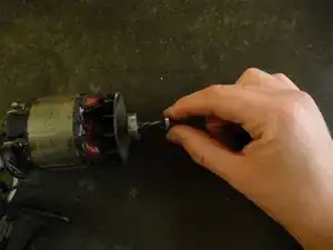
Place the ball bearing ring on the opposite end of the armature.
-
-
-
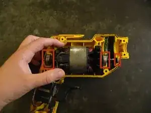
Place the motor back into the bottom half of the clamshell case.
-
Make sure the three ball bearings are aligned with their receptors. Slightly adjusting the armature inside the field may be necessary.
-
-
-
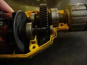
Replace the spindle and gear assembly.
-
Lift and adjust until the two helical gears are meshed properly.
-
-
-
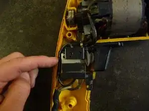
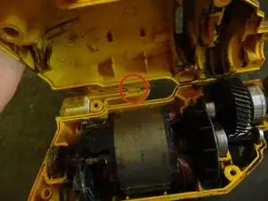
Place the switch into the slot.
-
Tuck the wiring both inside the edge of the case and out of the way of the support pegs.
-
-
-
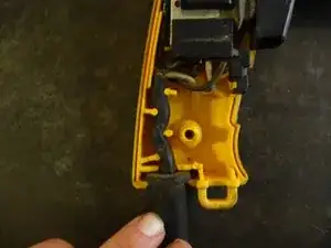
Thread the power cord through the support pegs.
-
Insert the top end of the cord protector into the slot.
-
-
-
Using the notch, align the two halves of the clamshell case and close it.
-
Pay special attention to ensure the wiring all stays clear of the support pegs and the ball bearing wheels and level all stay in their slots.
-
-
-
Rescrew all seven screws using the T20 driver.
-
To ensure a tight fit, use the T-handle configuration on the screwdriver.
-
Plug it in and see if it works more reliably.
Ein Kommentar
Will try tomorrow, thanks in advance!
