Einleitung
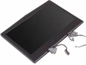
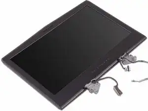
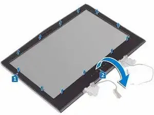
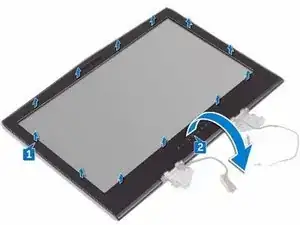
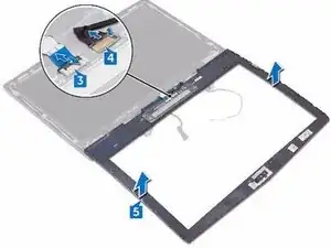
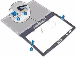
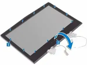
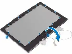
In this guide, we will show you how to remove and replace the Display Bezel.
Werkzeuge
-
-
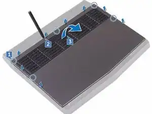
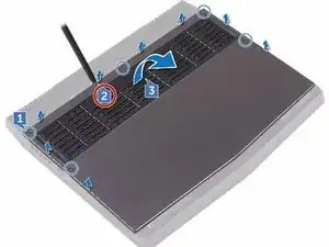
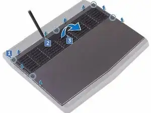
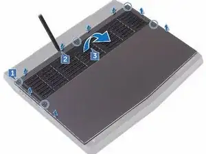
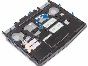
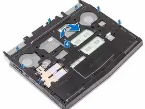
Using a plastic scribe, gently pry the base cover to release the tabs on the base cover from the slots on the computer base.
-
-
-
Slide the tabs on the NEW base cover into the slots on the computer base and snap the base cover into place
-
-
-
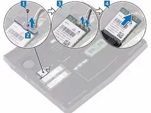
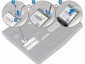
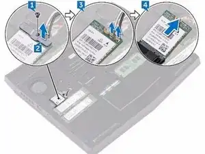
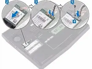
Align the screw hole on the wireless-card bracket with the screw hole on the wireless card and the computer base.
-
-
-
Replace the screw (M2x3) that secures the wireless-card bracket to the wireless card and the computer base.
-
-
-
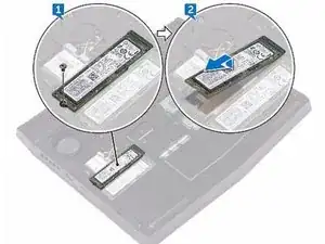
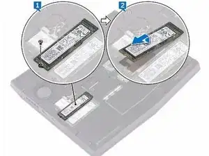
Align the notch on the NEW solid-state drive with the tab on the solid-state drive slot and slide the solid-state drive into the solid-state drive slot.
-
-
-
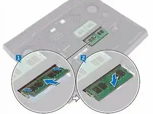
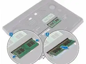
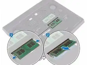
Using your fingertips, carefully spread apart the securing clips on each end of the memory-module slot until the memory module pops up.
-
-
-
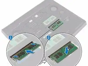
Align the notch on the NEW memory module with the tab on the memory-module slot and slide the memory module firmly into the slot at an angle.
-
-
-
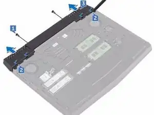
Remove the two screws (M2.5x6L) that secure the rear-I/O cover to the palm-rest assembly.
-
-
-
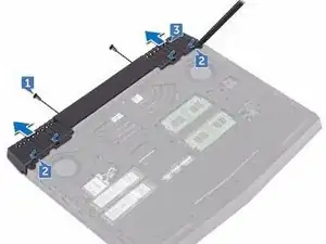
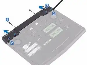
Using a plastic scribe, gently release the tabs that secure rear-I/O cover to the computer base.
-
-
-
Slide the NEW rear-I/O cover into the slots on the computer base and snap the rear-I/O cover into place.
-
-
-
Replace the two screws (M2.5x6L) that secure the rear-I/O cover to the palm-rest assembly.
-
-
-
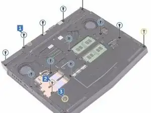
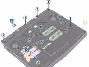
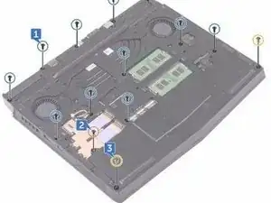
Remove the eleven (M2.5x6L) screws that secure the computer base to the palm-rest assembly.
-
-
-
Align the screw holes on the NEW computer base with the screw holes on the palm-rest assembly.
-
-
-
Replace the two (M2.5x6L) screws that secure the computer base to the palm-rest assembly.
-
-
-
Replace the eleven (M2.5x6L) screws that secure the computer base to the palm-rest assembly.
-
-
-
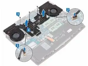
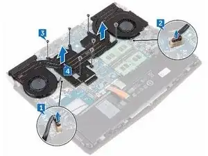
In sequential order (as indicated on the heat-sink assembly), remove the seven screws (M2x3) that secure the heat-sink assembly to the system board.
-
-
-
Align the screw holes on the NEW heat-sink assembly with the screw holes on the system board.
-
-
-
In sequential order (indicated on the heat-sink assembly), replace the seven screws (M2x3) that secure the heat-sink assembly to the system board.
-
-
-
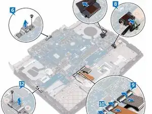
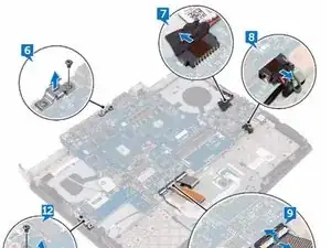
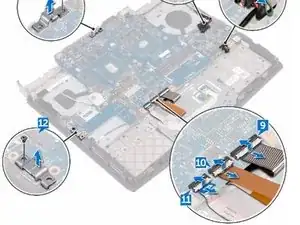
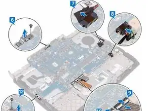
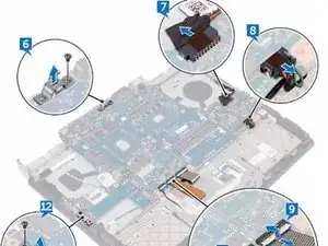
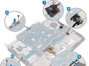
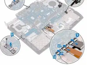
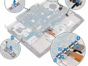
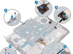
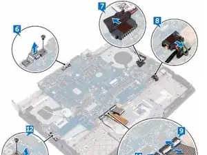
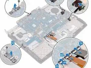
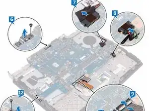
Remove the screw (M2.5x6L) that secures the USB Type-C port bracket to the system board and lift the USB Type-C port bracket off the system board.
-
-
-
Remove the screw (M2.5x6L) that secures the USB Type-C port bracket to the system board and lift the USB Type-C port bracket off the system board.
-
-
-
Align the screw holes on the NEW system board with the screw holes on the palm- rest assembly.
-
-
-
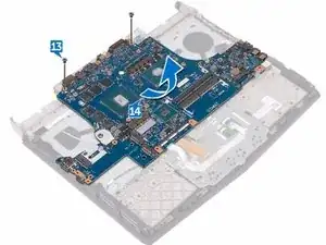
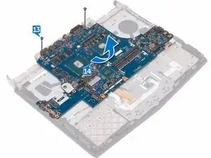
Replace the two screws (M2.5x6L) that secure the system-board to the palm- rest assembly.
-
-
-
Align the screw hole on the USB Type-C port bracket with the screw hole on the system board on the back and right side of your computer.
-
-
-
Replace the screw (M2.5x6L) that secures the USB Type-C port bracket to the system board on the back and right side of your computer.
-
-
-
Slide the touch-pad cable into the connector on the system board and close the latch to secure the cable.
-
-
-
Slide the keyboard-backlight cable into the connector on the system board and close the latch to secure the cable.
-
-
-
Slide the keyboard cable into the connector on the system board and close the latch to secure the cable.
-
-
-
Slide the display cable into the connector on the system board and close the latch to secure the cable.
-
-
-
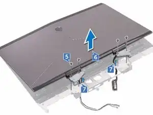
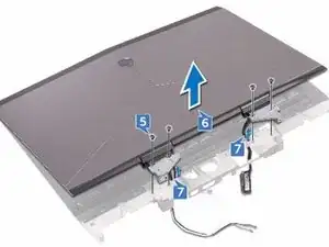
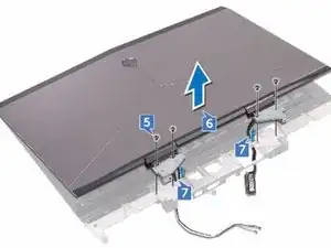
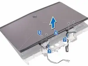
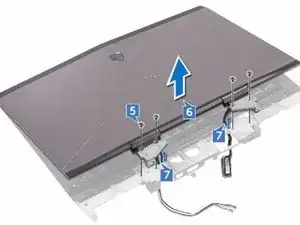
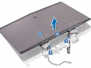
Remove the four screws (M2.5x6L) that secure the display assembly to the palm-rest assembly.
-
-
-
Align the screw holes on the display hinges with the screw holes on the palm- rest assembly.
-
-
-
Replace the four screws (M2.5x6L) that secure the display assembly to the palm-rest assembly.
-
-
-
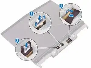
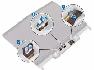
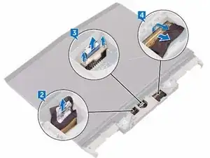
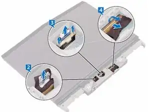
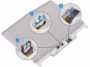
Peel off the tape that secures the logo-board cable to the logo board and disconnect the logo-board cable from the logo board.
-
-
-
Slide the alien head logo-board cable into the logo board and close the latch to secure the cable.
-
-
-
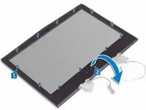
Align the display bezel with the display back-cover and antenna assembly and gently snap the display bezel into place.
-
To reassemble your device, follow these instructions in reverse order.

