Einleitung

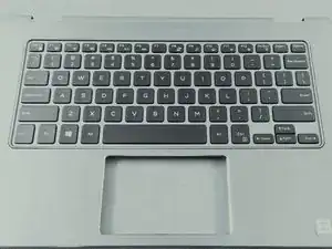
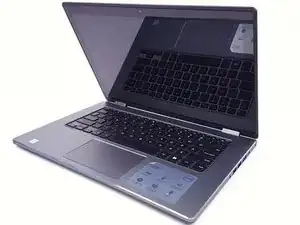
A misfunctioning or broken Keyboard and/or Touchpad is actually an inexpensive fix that may save you from having to throw away an otherwise working device.

Please review attached safety information before beginning repair.

Safety

Please review safety information found here before working on your device.

  1. Y4uUed5TXl1VDgbJ
    Y4uUed5TXl1VDgbJ
    KX1SuOSKJetBKWv3
    CKYmjFJkNfangDNe
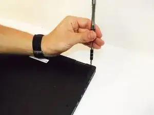
    • Remove the 10 - M2.5 x 8mm screws located on the bottom of the device.

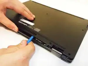
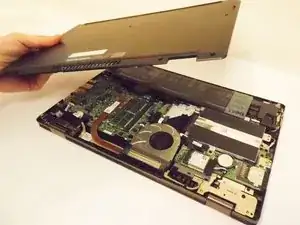
    • Detach and remove the Bottom Base Cover using an opening tool to pry it off.

  2. SPH4jLigykdtNpVj
    SPH4jLigykdtNpVj
    sTRLBoUGuKkcgAHu
    kfEGNTPaoKFJPyCE
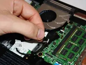
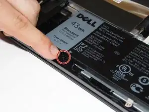
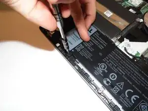
    • Unplug and gently pull the hard drive cable to loosen it.

    • Remove the 2 - M2 x 3mm screws.

    • Remove the Battery.

  3. aIOTglQwOUVXsNtN
    aIOTglQwOUVXsNtN
    RMxCXoC1eEASxItL
    xlMHPYQsAAIhfqHO
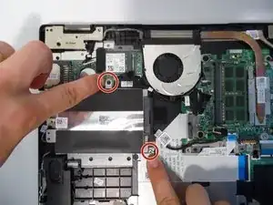
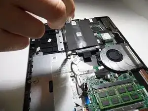
    • Remove the 2 - M2 x 3mm hard drive screws.

    • Remove the Hard Drive.

  4. qgo6ROYiGSMb3B5G
    qgo6ROYiGSMb3B5G
    POvJtpsskRtDNH3a
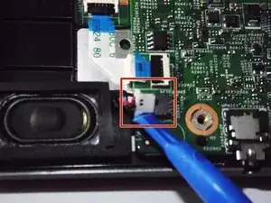
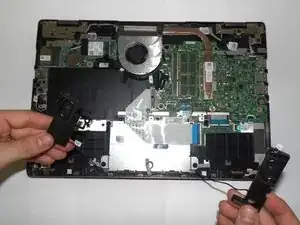
    • Unplug the speaker cable.

    • Remove the Speakers.

  5. p1wPh6kuJHQFuUar
    p1wPh6kuJHQFuUar
    mMGAjwVHmiigX3yF
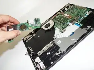
    • Unplug the fan cable.

    • Unplug and remove the daughter board cable.

  6. N6kDWG4TQa4RHwZb
    N6kDWG4TQa4RHwZb
    15OenSfbXcK2KZwe
    YDYEjjhZEDxasBWM
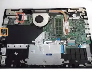
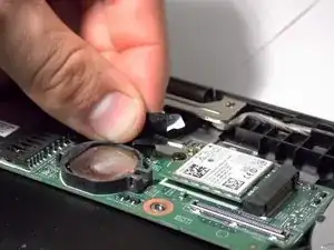
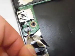
    • Unplug the antenna cables.

    • Unplug the power button cable.

  7. TNAe3aaWuPvx4G1d
    TNAe3aaWuPvx4G1d
    wBnKOpQrFYdLNPPC
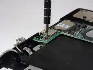
    • Remove the 1 - M2 x 3mm screw.

    • Remove the USB / SD Card Circuit Board.

  8. jtuPRchOMfdQOHAV
    jtuPRchOMfdQOHAV
    ucfJir66skaFBLZZ
    W5DTVPw2IDbhpKau
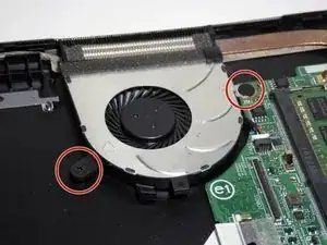
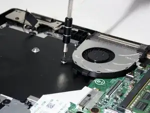
    • Remove the 1 - M2 x 3mm and 1 - M2 x 2mm Wafer screw.

    • Remove the Cooling Fan.

  9. TaZ4UJ3ZaAnY1D2r
    TaZ4UJ3ZaAnY1D2r
    kkSpSSvRRbXSbAMS
    EO41HwFjDRgPpVdg
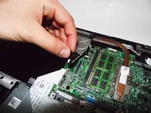
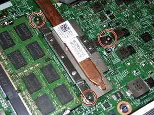
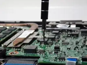
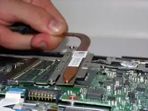
    • Loosen the screws.

    • Remove the Heatsink.

  10. IDqdxGOBNuRlN11F
    IDqdxGOBNuRlN11F
    tq33xJwSUPu5lHyM
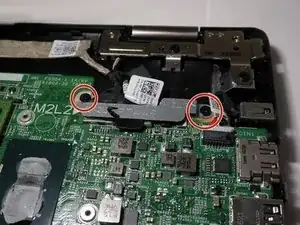
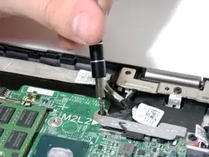
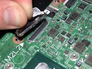
    • Remove the 2 - M2 x 3mm bracket screws.

    • Remove the LCD cable bracket.

  11. ifNYNFNbO6b6Bub5
    ifNYNFNbO6b6Bub5
    AA2yZLdVytcubgrT
    • Unplug the LCD cable.

    • Unplug the touchscreen cable.

  12. JKY1ZUpXrWmCfMtm
    JKY1ZUpXrWmCfMtm
    nMWhRQXMEboQuEDy
    nxh1JKgFXJiweIyY
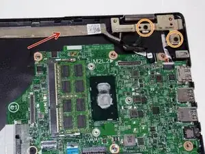
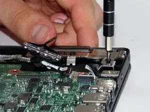
    • Open the screen.

    • Loosen the LCD cable and peel it off of the base (highlighted with arrow).

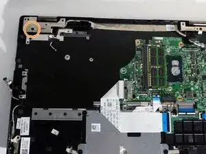
    • Remove the 3 - M2.5 x 8mm hinge screws.

  13. hkVVKNcPAJjhTtxJ
    hkVVKNcPAJjhTtxJ
    XZSPoyaqXIkJEdFR
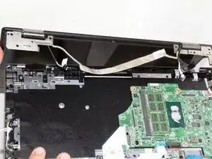
    • Remove the screen assembly.

    • You may need to pull the hinges up.

  14. DObZiwAe1QMJan4M
    DObZiwAe1QMJan4M
    N2W52kFKbfvFOY3v
    rLrBrUoNmVQNXXUn
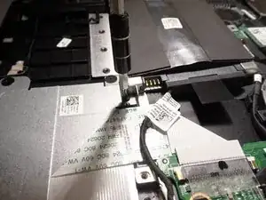
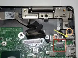
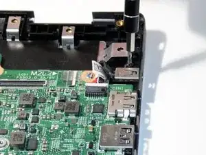
    • Unplug the cable.

    • Remove the 1 - M2 x 3mm screw.

    • Remove the DC Jack.

  15. kijYbg26BHUVipNK
    kijYbg26BHUVipNK
    GiMSAYjWYxfMtMCm
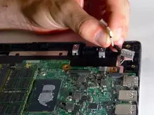
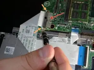
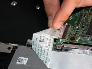
    • Loosen the keyboard cable tape.

    • Loosen the keyboard cable latches.

    • Unplug the keyboard cable.

  16. AvV2VUPSGHDWWUCS
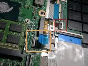
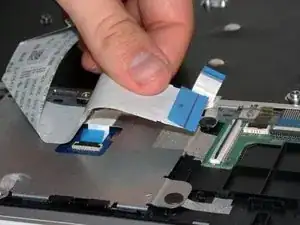
    • Unplug the keyboard backlight cable.

    • Unplug the touchpad cable.

  17. o1Pn1kEJ23QdEbZP
    o1Pn1kEJ23QdEbZP
    yhrwUDJQMGD6GYXH
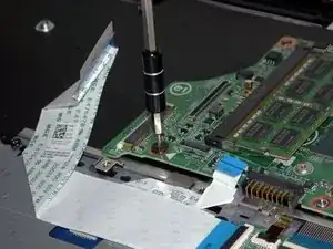
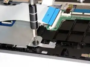
    • Remove the 1 - M2 x 2mm Wafer screw.

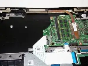
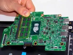
    • Remove the Motherboard.

    • The piece remaining is the Palmrest Keyboard.

  18. SvZXCRjQisncAbcl
    • You can further disassemble by removing the touchpad.

    • Unplug the touchpad cable.

  19. rFUcRvdyBYcUX5Id
    rFUcRvdyBYcUX5Id
    YQsjD4kgZbDXhhTS
    mos4JHjleHWYHmPs
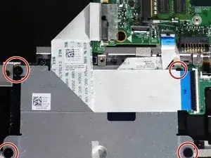
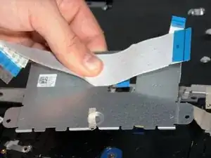
    • Unscrew the 4 - 2x2mm wafer screws.

    • Peel back any tape holding the back plate on.

    • Lift and remove back plate.

  20. YVZQnJflLH3COCkK
    YVZQnJflLH3COCkK
    oRwHXawWKTH4krfH
    SWSoTMNPPX6xnXCB
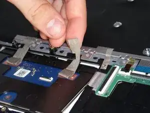
    • Peel back under-button tape.

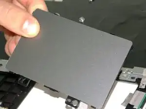
    • Remove touchpad.

    • You have now stripped the keyboard! It is ready to be replaced.

Abschluss

To reassemble your device, follow these instructions in reverse order.
Taylor Hunter

Mitglied seit: 01/04/17

143 Reputation

0 Kommentare