Einleitung
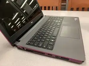
This iFixit guide covers the replacement of a the palm-rest assembly from an Inspiron 15-5558 laptop. Please note that screws have been assembled by the manufacturer with blue Loctite to prevent the backing out of screws over time. This means that screws may initially be difficult to start to turn, but should not cause additional issues .
Also while working with sensitive electronics, it is important not to introduce additional debris to the inside of a laptop and to occasionally ground yourself by touching a metal object to prevent static discharge.
Werkzeuge
-
-
Eject the CD tray while the laptop is on.
-
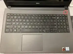
Turn off the laptop using the power button.
-
Or remove the 2x5 securing screw and push through the battery compartment to slide the optical drive out.
-
-
-
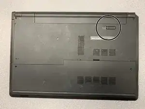
Move the unlocking switch to the left to eject the battery.
-
The battery is designed to rotate slightly before lifting out.
-
Remove the 2.5x5 screws inside the compartment.
-
-
-
Turn the laptop over and open up the front screen to show the keyboard.
-
Use a (Philips) flathead near the top, center of the keyboard to begin popping out the keyboard.
-
Remove the bottom tabs of the keyboard by pulling the keyboard up towards the screen.
-
-
-
Carefully lift up the keyboard
-
There should be cables hooked to underside of the keyboard.
-
Remove tape, if there is tape, and disconnect all flaps and cables by lifting up.
-
-
-
Use Phillips #00 screwdriver to remove 2.5 x 8 screws securing the base cover.
-
Use the 3/32 Flathead screwdriver to gently pry off the base cover around the top , slotted section .
-
-
-
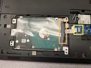
Remove screws securing the hard drive to the laptop.
-
Disconnect the black cable by pulling it away from the hard drive.
-
Lift the black latch to unlock the cable.
-
Remove the hard drive cable from the lower, blue circuit board
-
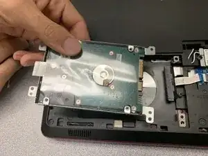
Remove the hard drive from the laptop.
-
Or, unlatching the cable lets you keep the black adapter attached to the hard drive to remove as one unit.
-
-
-
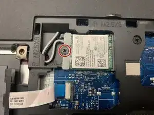
Unscrew the M2x3 screw
-
Lift off wireless card bracket
-
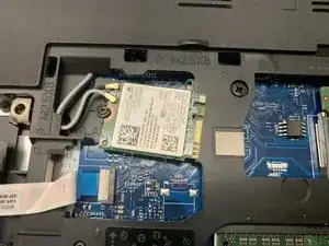
Gently unplug the wireless card by pulling it out to the left
-
Disconnect the black and white antenna cables
-
-
-
Remove the screws securing the palmrest and base.
-
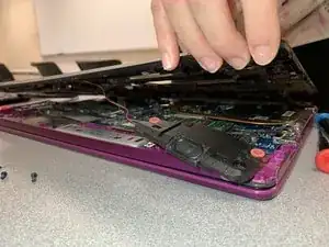
Use the Philips flathead and your hands to lift up the computer base.
-
Be careful to lift up the keyboard around the hinges.
-
-
-
The speakers may be removed from the computer base by unattaching from the computer base or disconnecting the cable and leaving the speakers on the computer base.
-
-
-
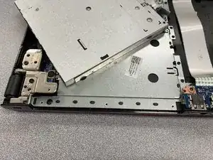
Disconnect the optical drive cable that is attached to the innermost layer of computer components.
-
While lifting up, unscrew all screws holding the optical drive to the computer base.
-
Remove the optical drive assembly
-
-
-
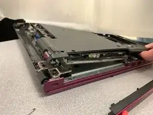
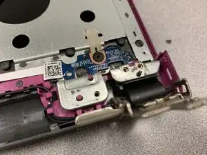
Unscrew all screws securing the left and right hinges.
-
Lift the hinges up towards the screen to expose the lower components.
-
-
-
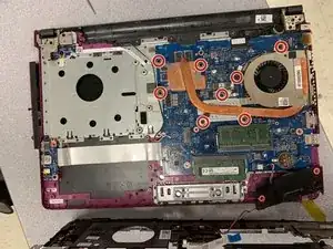
Unscrew the following screws from the motherboard and heatsink.
-
Disconnect the power button cable.
-
Lift from the laptop the motherboard and the heatsink assembly.
-
-
-
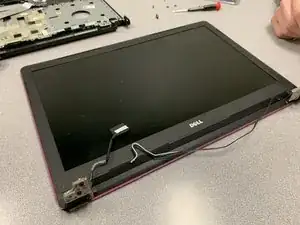
Remove the screen from the lower assembly by lifting it up from the now disconnected right and left hinges.
-
-
-
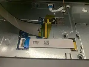
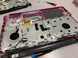
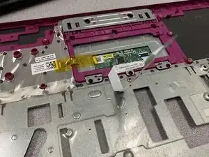
Take off the two gold pieces of tape.
-
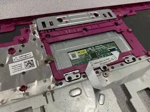
Unscrew the circuit board near the left hinge, when looking at the laptop from the front. (This is connected to the mousepad)
-
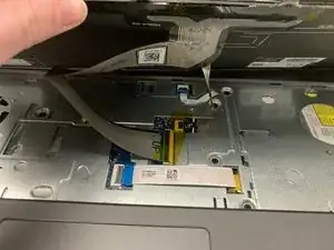
Remove tape and lift off the black and white antenna cables starting at the mousepad to the left hinge.
-
Take off the tan golden tape.
-
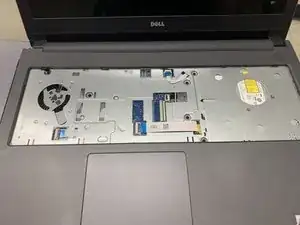
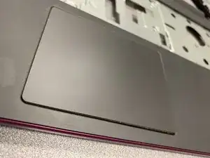
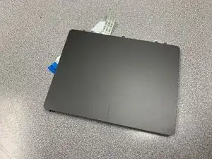
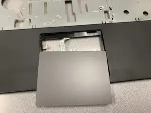
From the back, pop out the mousepad from the assembly. Be careful to lift out the tabs correctly.
-
-
-
Remove the original palm-rest assembly component from the laptop
-
Get out the replacement palm-rest assembly component.
-
-
-
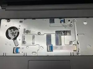
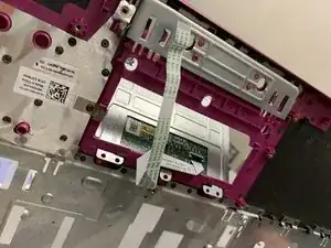
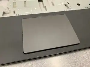
Fit the mousepad into the new palm-rest assembly component from the front of the laptop
-
Make sure to fit the cables through the back.
-
Put golden tape back on.
-
Adjust the cable for the mousepad back through slots on the internal side of the palm-rest assembly
-
To reassemble your device, follow these instructions in reverse order with the new replacement palm-rest assembly component.
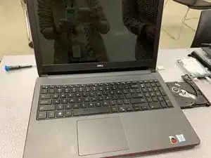
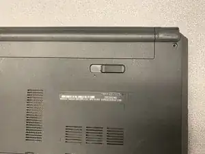
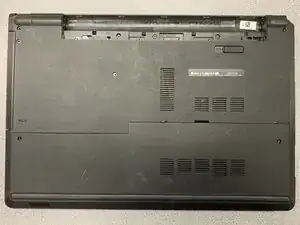
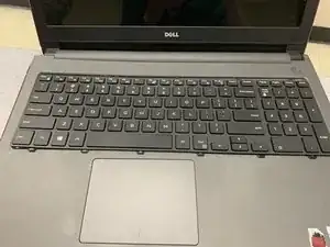
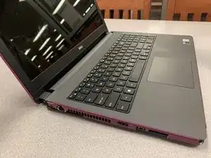
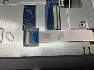
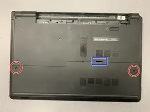
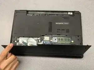
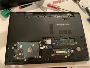
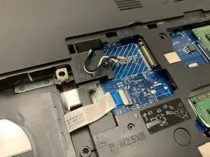
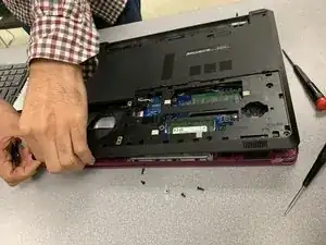
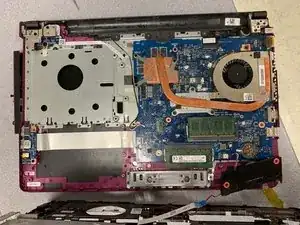
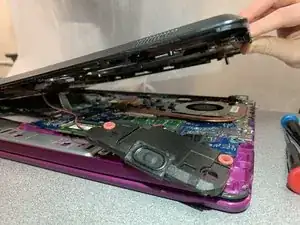
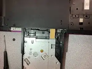
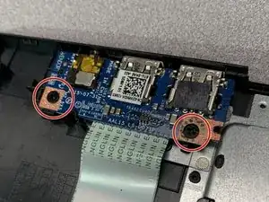
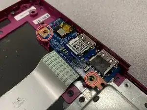
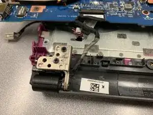
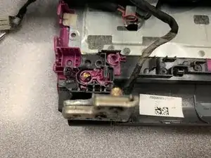
I was able to remove my optical drive by pushing it out after removing the 2x5 securing screw.
Carl -