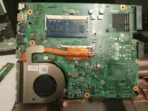
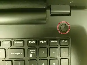
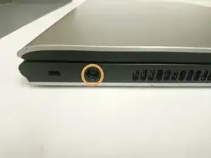
Einleitung
Werkzeuge
-
-
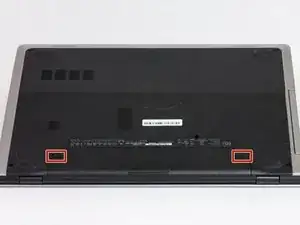
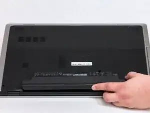
Switch each of the battery latches to the "unlocked" position.
-
Pull battery upwards by the tab to remove from the laptop.
-
-
-
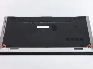
Remove the two 5.5mm screws that secure the base cover to the computer's base.
-
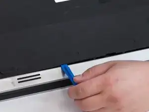
Using the plastic opening tool, carefully pry open the base cover starting from the center.
-
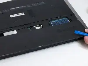
Lift the base cover upwards to remove and set it aside.
-
-
-
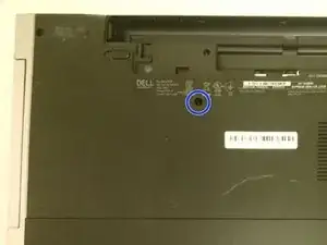
Remove the 5.5mm screw that secures the optical-drive assembly to the computer base
-
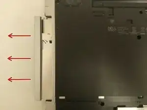
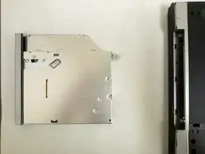
Using your fingertips, slide the optical-drive assembly out of the optical drive bay.
-
-
-
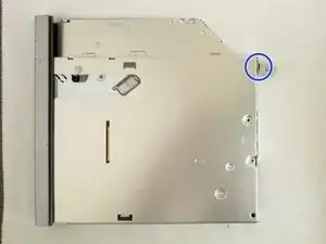
Remove the 2.5mm screw that secures the optical-drive bracket to the optical drive assembly.
-
Remove the optical-drive bracket from the optical-drive assembly.
-
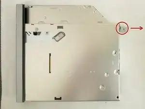
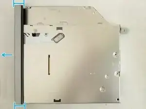
Carefully pull the optical-drive bezel and remove it from the optical drive.
-
-
-
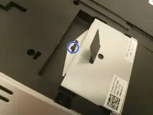
Remove the 2.5mm screw that secures the hard-drive assembly to the computer base.
-
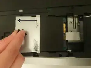
Using the pull tab, slide the hard-drive assembly to disconnect it from the system board.
-
Lift the hard-drive assembly off the computer base
-
-
-
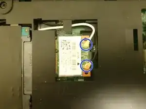
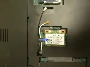
Disconnect the antenna cables from the wireless card.
-
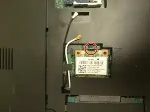
Push the securing tab to release the wireless card.
-
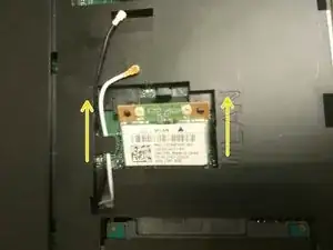
Slide the wireless card out of the wireless-card slot.
-
-
-
Turn the computer over and open the display as far as possible
-
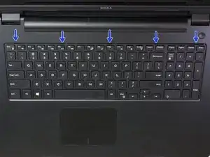
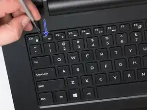
Using a plastic opening tool, release the tabs that secure the keyboard to the palm-rest assembly.
-
-
-
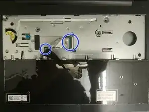
Carefully turn the keyboard over and place it on the palm rest assembly.
-
Lift the latches and disconnect the keyboard cable and keyboard back-light cable from the system board.
-
Lift the keyboard along with the cables, off the palm-rest assembly and set it aside.
-
-
-
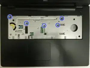
Remove the (5) 5.5mm screws that secure the palm rest to the system board.
-
Close the display and turn the computer over.
-
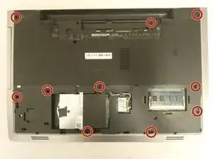
Remove the (10) 5.5mm screws that secure the palm rest to the computer base.
-
-
-
Turn the computer over and open the display as far as possible.
-
Lift the connector latches and disconnect the power-button board cable and the touch-pad cable from the system board.
-
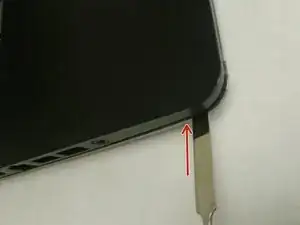
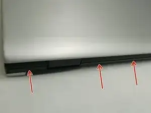
Using a plastic scribe, gently lift and release the tabs on the palm rest around the computer base including the backside.
-
Lift the palm rest away from the display assembly.
-
-
-
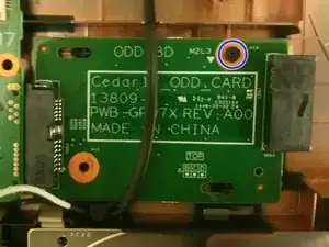
Remove the 2.5mm screw that secures the optical-drive connector board to the computer base.
-
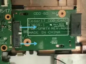
Move wireless card wires covering the board away from the board.
-
Slide the optical-drive connector board away from the computer base.
-
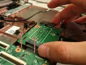
Lift the optical-drive connector board away from the computer base.
-
-
-
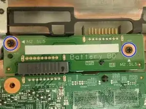
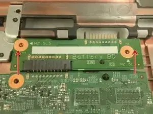
Remove the 5.5mm screws that secure the battery-connector board to the computer base.
-
Carefully lift the battery-connector board to disconnect it from the system board.
-
-
-
Close the display and turn the computer over.
-
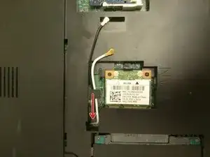
Remove the antenna cables from the routing guides on the computer base.
-
Slide the antenna cables through the slot on the computer base.
-
-
-
Turn the computer over and open the display as far as possible.
-
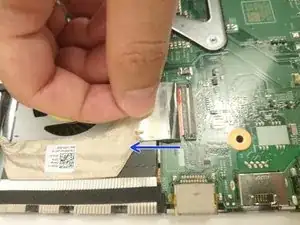
Peel off the tape that secures the display cable to the system-board assembly.
-
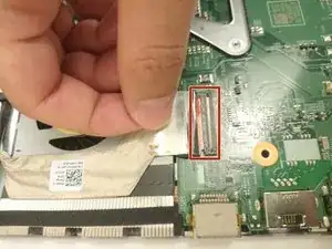
Lift the connector latch and disconnect the display cable from the system board.
-
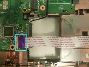
Lift the connector latch and disconnect the I/O board cable from the system board.
-
-
-
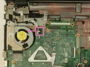
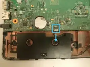
Disconnect the speaker cable from the system board.
-
Disconnect the power-adapter port cable from the system board.
-
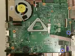
Remove the 5.5mm screws that secure the system-board assembly to the computer base.
-
Lift the system-board assembly off the computer base.
-
To reassemble your device, follow these instructions in reverse order.
