Einleitung
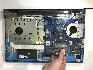
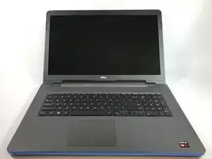
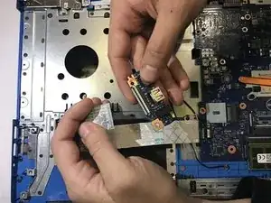
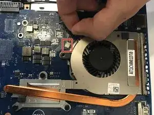
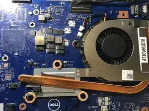
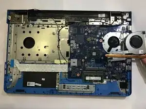
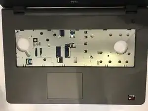
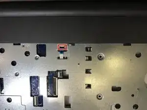
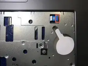
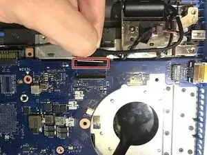
This guide will allow you to replace a defective motherboard for the Dell Inspiron 17-5755. Please ensure that the battery is removed before performing this replacement.
Werkzeuge
-
-
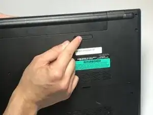
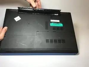
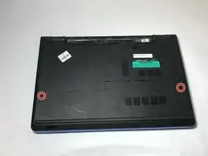
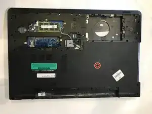
Find the battery release latch on the bottom side of the computer.
-
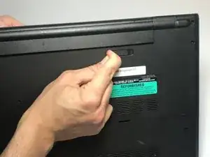
Slide the latch to the left until you hear a "click". This indicates that the battery has been released.
-
-
-
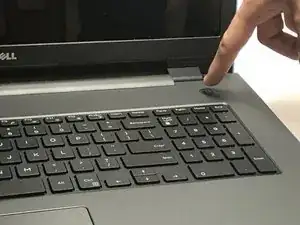
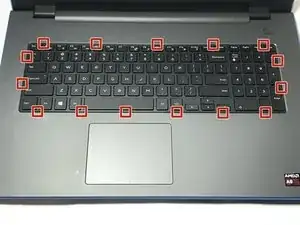
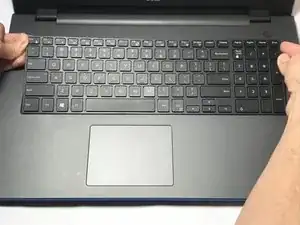
Open the display of the laptop as far as possible, and locate the tabs which secure the keyboard to the laptop.
-
-
-
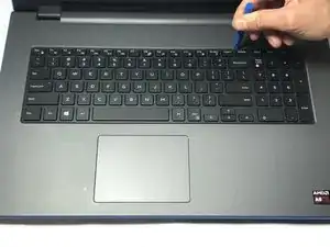
Use a plastic opening tool to gently release the tabs that secure the keyboard to the laptop.
-
-
-
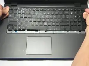
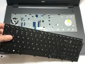
Carefully lift the keyboard from the laptop, being mindful of any attachments that it may have.
-
-
-
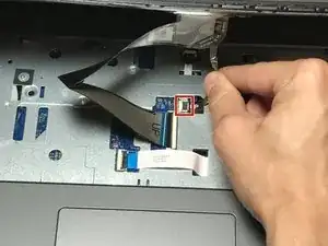
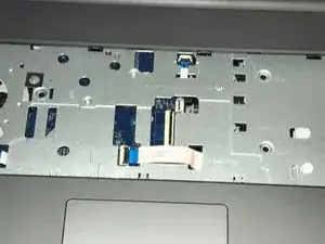
Lift the zero insertion force (ZIF) tab that secures the keyboard back light ribbon cable
-
Afterwards, carefully detach the backlight cable from the laptop.
-
-
-
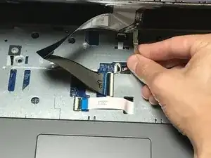
Gently release the ZIF tab that secures the keyboard ribbon cable to the laptop.
-
Afterwards, carefully slide the cable out of its slot.
-
-
-
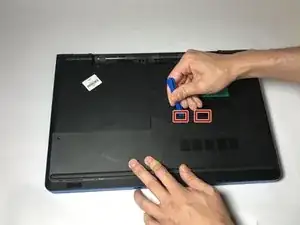
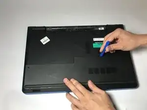
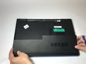
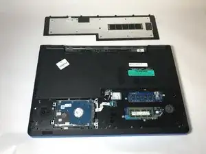
Locate the tabs that hold the base cover to the laptop and use a plastic opening tool to gently release the base cover.
-
-
-
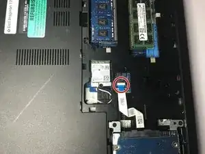
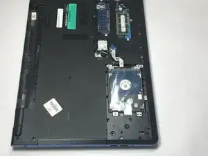
Disconnect the hard drive ribbon cable from the laptop by lifting the latch which secures it.
-
-
-
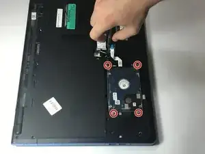
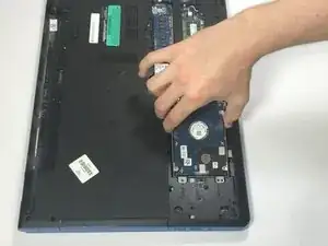
Use a Phillips #0 screwdriver to remove the four 8mm screws which secure the hard drive assembly to the laptop.
-
-
-
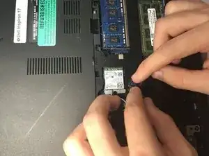
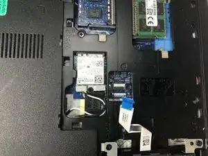
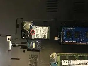
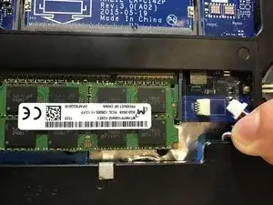
Remove the 3mm screw which secures the wireless card bracket.
-
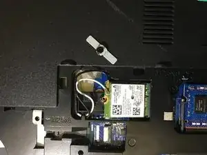
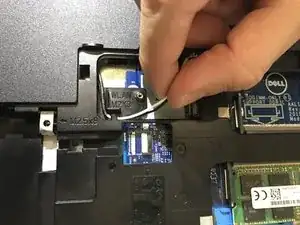
After removing the screw, remove the wireless card bracket, along with the antenna cables secured to the wireless card.
-
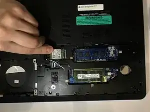
Afterwards, you may slide and remove the wireless card from the motherboard.
-
-
-
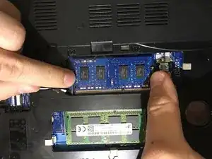
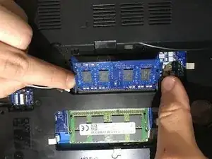
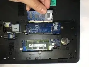
Gently spread apart the securing clips on each end of the memory-module slot until the memory module pops out.
-
Slide and remove the memory module afterwards.
-
-
-
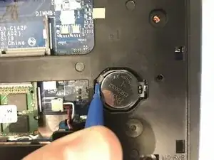
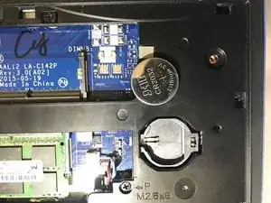
Use a plastic opening tool to gently pry the CMOS battery found at the bottom right of the laptop out of the socket.
-
-
-
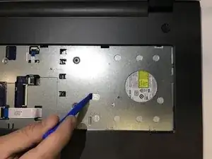
Use a Phillips #0 screwdriver to remove the 3mm screw which secures the optical-drive assembly to the computer base
-
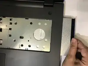
Turn the computer over and using a plastic opening tool, push the optical-drive assembly out of the optical drive bay.
-
Afterwards, safely pull the optical-drive assembly out of the optical-drive bay.
-
-
-
Turn the computer over
-
Lift the latch securing the optical drive ribbon cable, and disconnect it from the motherboard.
-
Afterwards, use a Phillips #0 screwdriver to remove the four 5mm screws.
-
-
-
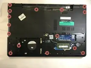
Use a Phillips #0 screwdriver to remove the 15 screws that secure the computer base to the palm rest assembly.
-
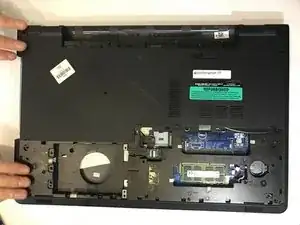
Afterwards, safely pry the computer base from the palm rest assembly using a plastic opening tool.
-
-
-
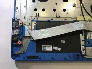
Use a Phillips #0 screwdriver to remove the 5mm screw that secures the I/O board to the palm-rest assembly.
-
-
-
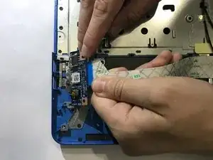
Lift the I/O board and turn it over.
-
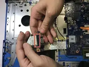
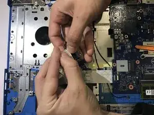
Afterwards, lift the ZIF latch and disconnect the I/O-board cable from the I/O board.
-
-
-
Disconnect the fan cable from the motherboard.
-
Use a Phillips #0 screwdriver to remove the heat-sink screws in sequential order, as indicated by the numbers on the heat-sink assembly.
-
Afterwards lift the heat-sink assembly off the motherboard.
-
-
-
Turn the computer over and open the display as far as possible.
-
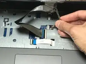
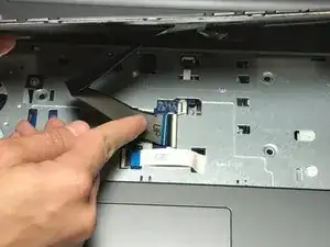
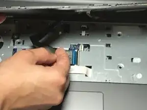
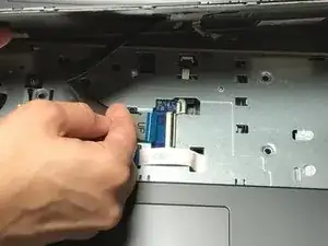
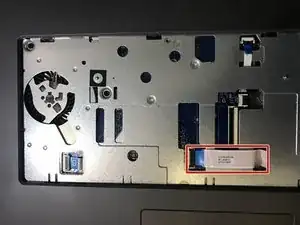
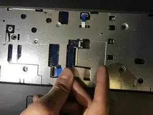
Lift the latches for the power button board cable and disconnect it along with the touchpad cable from the motherboard.
-
-
-
Close the display and turn the computer over.
-
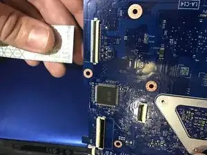
Proceed to lift the latch which secures the ZIF display cable to the motherboard.
-
Disconnect the display cable from the motherboard.
-
-
-
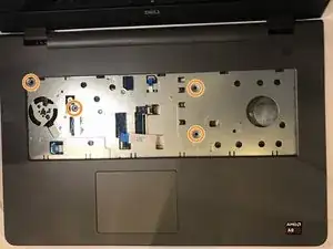
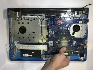
Use a Phillips# 0 screwdriver to remove the 3mm screw that secures the motherboard to the palm-rest assembly.
-
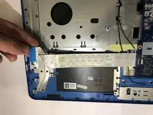
Afterwards, carefully peel the I/O board cable off the palm-rest assembly.
-
-
-
Turn the motherboard over.
-
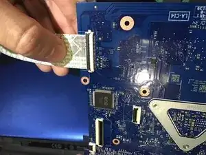
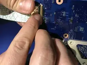
Lift the latch to disconnect the I/O-board cable from the motherboard.
-
-
-
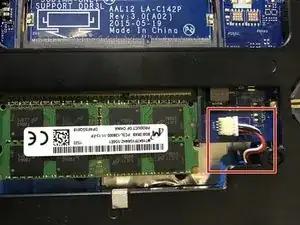
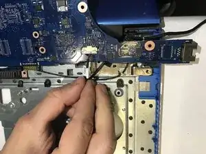
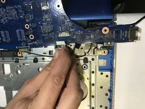
Disconnect the power-adapter port cable from the motherboard.
-
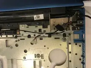
Afterwards you may safely remove the motherboard from the laptop.
-
To reassemble your device, follow these instructions in reverse order.
